Solved

“Clipper” fails to generate proper geometry in simple AutoCAD file,


jamal
Forum|alt.badge.img+5
“Clipper” fails to generate proper geometry in simple AutoCAD file,


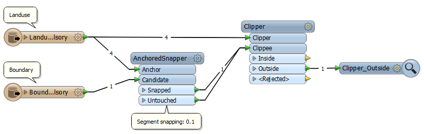
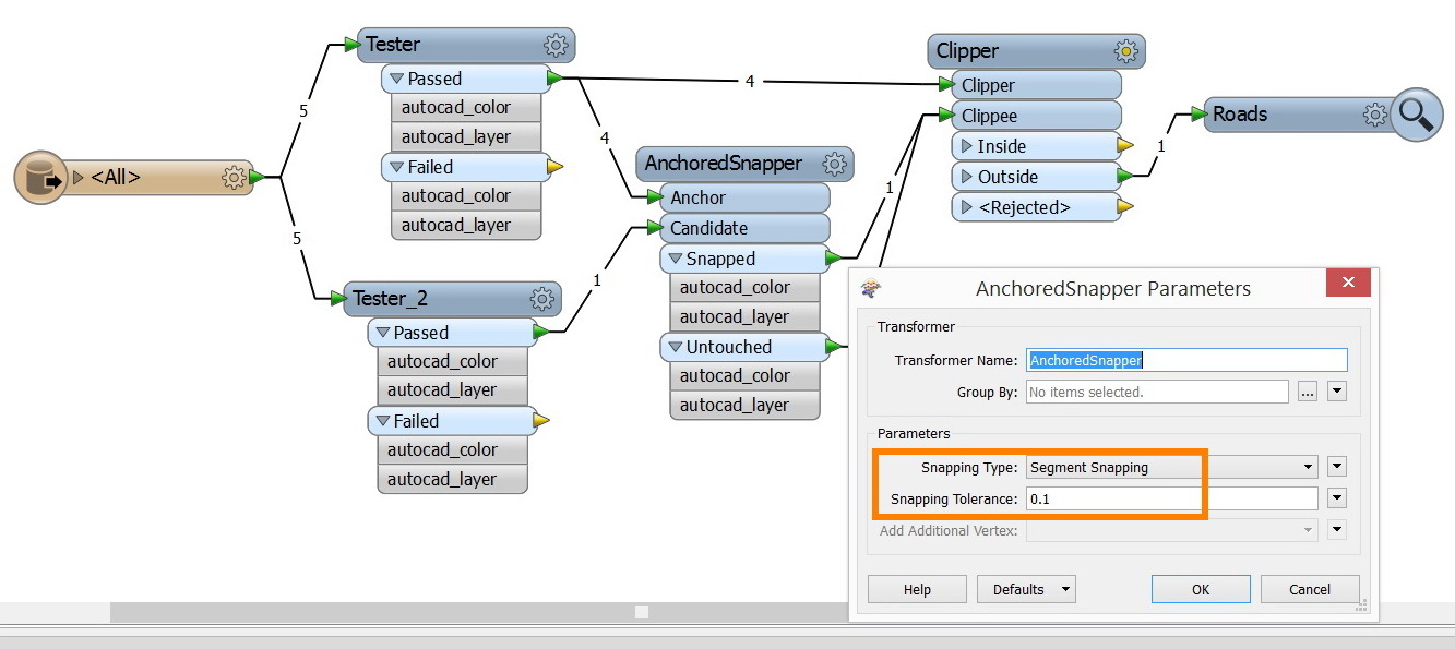
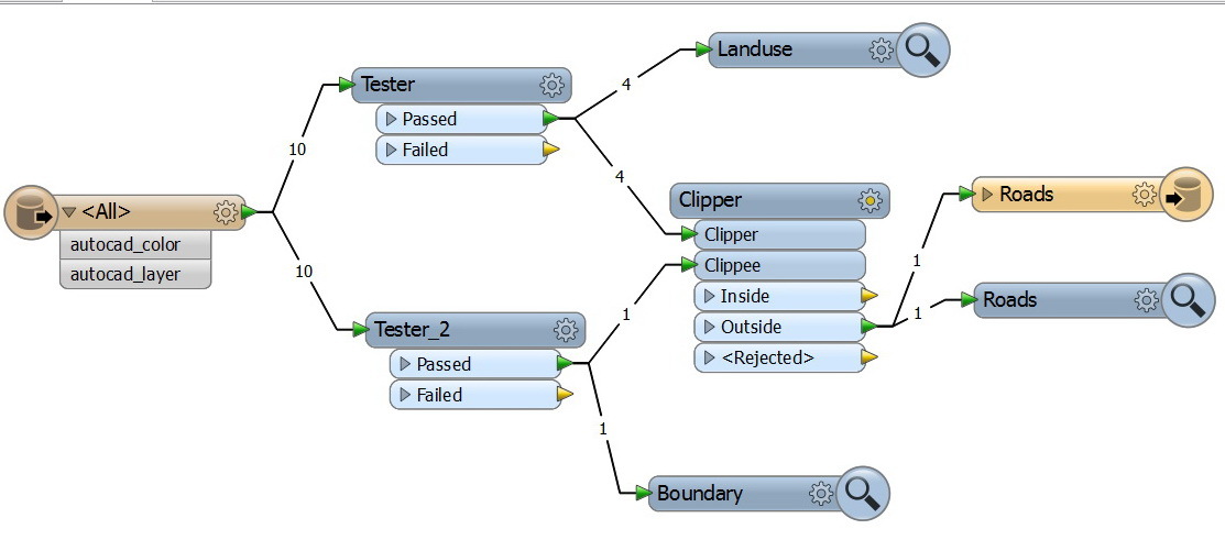
I wanted to extract the Roads from the Boundary and Landuse


Mathematically


Roads = Boundary – Landuse


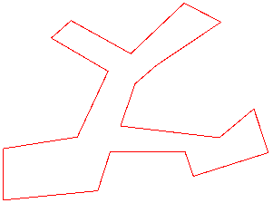
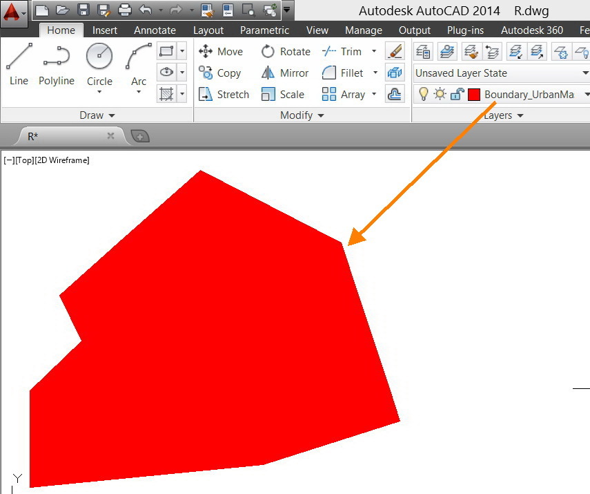
The Boundary layer (contains 1 hatch only) is properly extracted


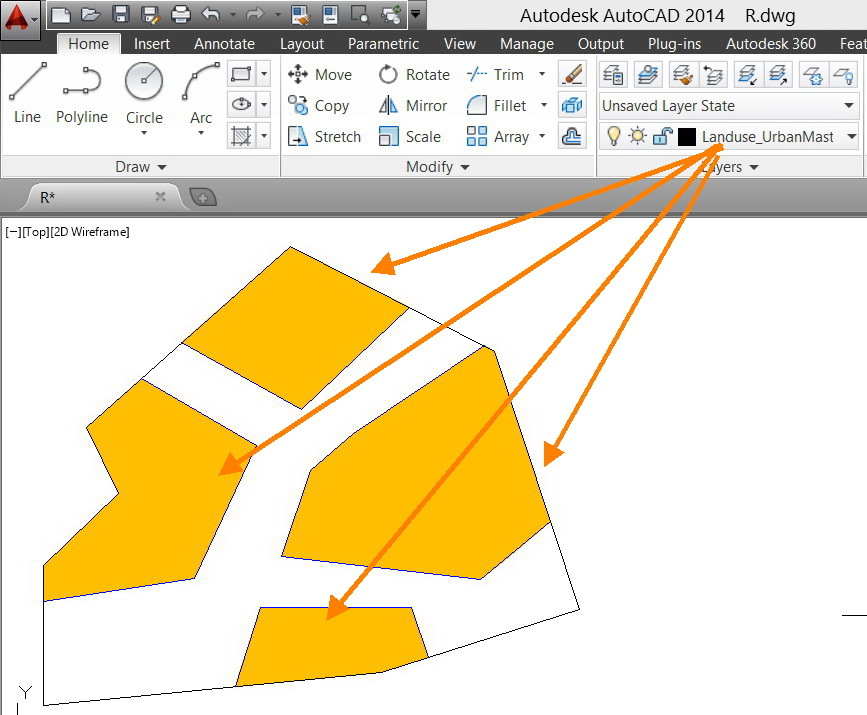
The Landuse (contains 4 hatches) is properly extracted too


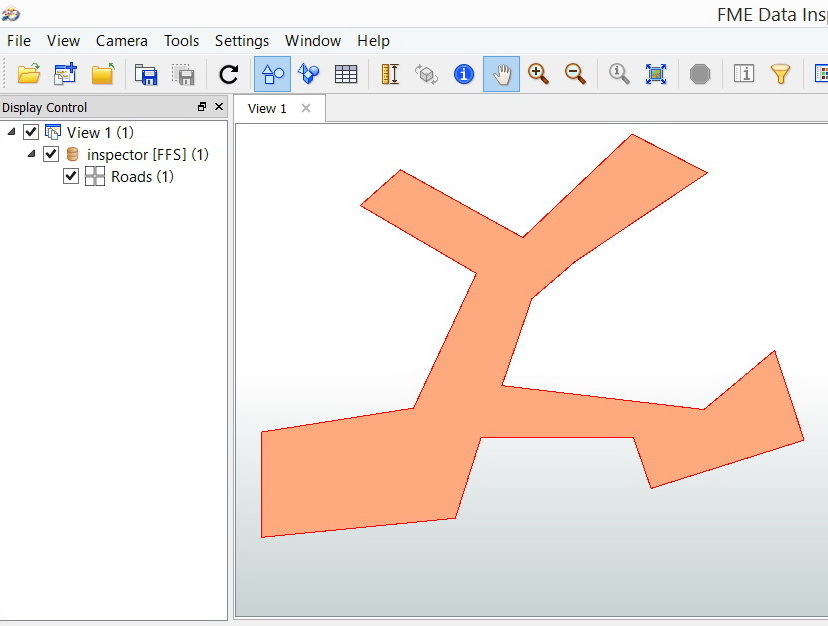
Now the Roads is improperly extracted. The results shows extra elements.


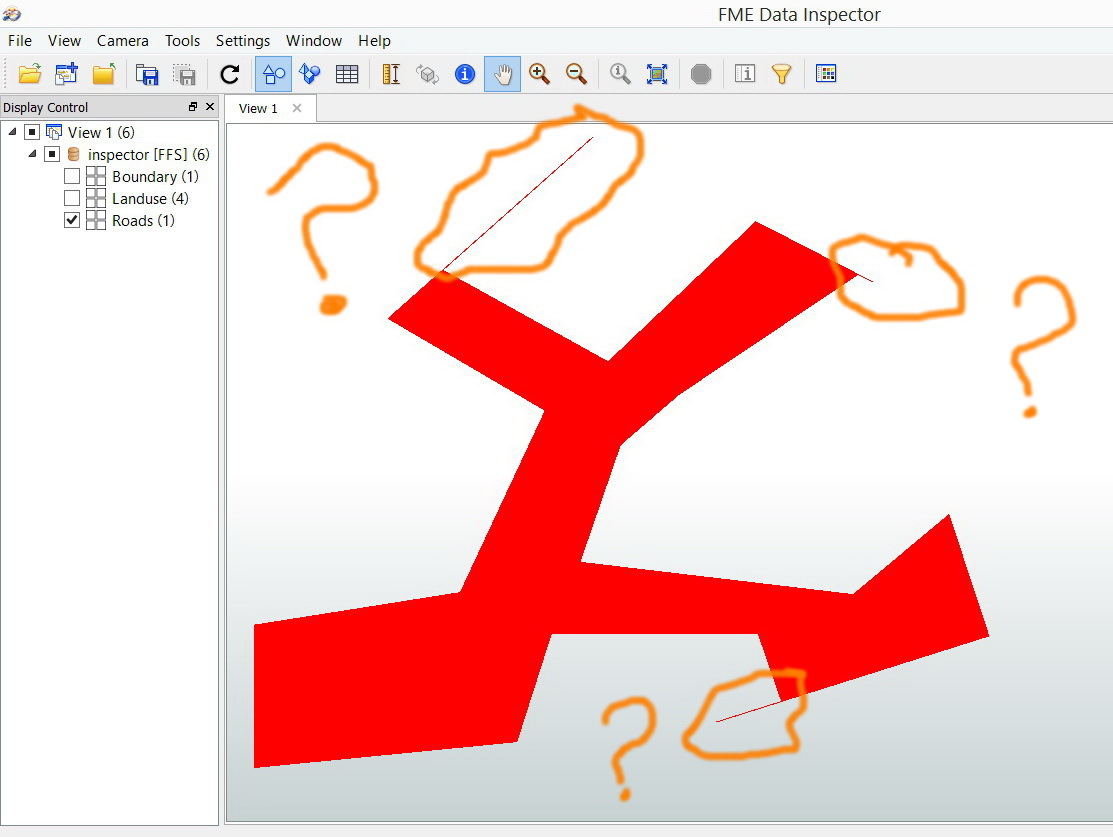
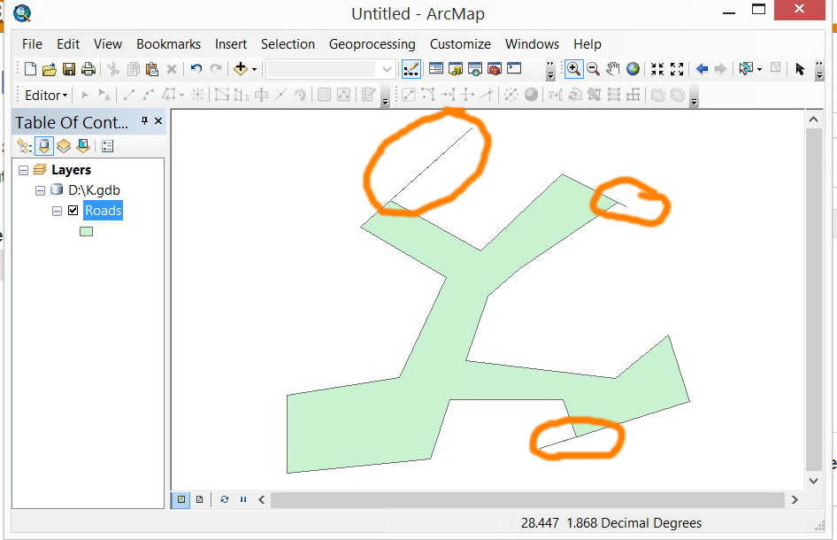
What might be the issue here?


CAD file


http://www.mediafire.com/download/bguke2k138n8516/R.dwg


Workbench:


http://www.mediafire.com/view/gov4uk7lkpnhu66/Landuse_Boundary_Roads.fmw


Thank you


Best


Jamal

Best answer by david_r

Here's an example:


Result:


David
View original
Did this help you find an answer to your question?
This post is closed to further activity.
It may be a question with a best answer, an implemented idea, or just a post needing no comment.
If you have a follow-up or related question, please post a new question or idea.
If there is a genuine update to be made, please contact us and request that the post is reopened.

4 replies

takashi
Influencer
  • March 12, 2014
Hi Jamal,


Probably such spikes were caused by the condition where boundaries of the Boundary and the Landuse are not matched exactly. I think that the result has reflected condition of the source data correctly.


If you don't like the spikes, try using the SpikeRemover to remove them. Alternatively, try shrinking the Boundary by a slight amount using the Bufferer before clipping.


Although modification might be possible, it depends on the requirement whether modified geometries are proper.


Takashi

david_r
Celebrity
  • March 12, 2014
Hi,


be aware that while some systems have a notion of precision (e.g. ArcGIS) and internally consider very close coordinates to be identical, this is not the case in FME, where the full precision is always used. This can lead to results as the one you're seeing here.


Rather than using the SpikeRemover (which might introduce other problems), I'd try to remove the inaccuracies before the Clipper. Try using the AnchoredSnapper with the Boundary layer as ANCHOR and the Land use layer as CANDIDATE. Set the snapping type to Segment snapping (2014) or Vertex snapping (earlier versions). Set the snapping tolerance equal to half your AutoCAD precision.


This will perfectly align both layers before the Clipper and should hopefully give you a perfect result.


David

david_r
Celebrity
  • Best Answer
  • March 12, 2014
Here's an example:


Result:


David

jamal
Forum|alt.badge.img+5
  • Author
  • March 14, 2014
Very much appreciated Takashi and David,


Perfect David. With the “AnchoredSnapper” the problem is vanished.


Cookie policy

We use cookies to enhance and personalize your experience. If you accept you agree to our full cookie policy. Learn more about our cookies.

 
Cookie settings