You can use the offsetter on a second stream of features to achieve that.
Optionally the offsetcurvegenerator can also be of use.
For simplifying the explanation, assume that the original line is a line segment having only 2 nodes (start (x0, y0) and end (x1, y1)) and its length is 100 ft..
1) Calculate the unit vector (ux, uy) of the original line segment. ux = (x1 - x0) / 100 uy = (y1 - y0) / 100 2) Create the left-side perpendicular line of 25 ft., move its starting point to the 13 ft. location along the original line from (x0, y0): Rotate the original line around (x0, y0) by 90 degree. Snip the beginning 25ft. of the rotated line. Offset the snipped line by (ux * 13, uy * 13). 3) Create the right-side perpendicular line of 20 ft., move its starting point to the 25 ft. location along the original line from (x0, y0): Rotate the original line around (x0, y0) by 270 degree. Snip the beginning 20 ft. of the rotated line. Offset the snipped line by (ux * 25, uy * 25).
Result:
To do this, consider using the CoordinateExtractor, LengthCalculator, ExpressionEvaluator (or AttributeCreator), Rotator, Snipper and Offsetter etc.. In addition, be aware that the result of division becomes an integer value if both of denominator and numerator are integer values. Use "@double" function to cast at least one operand of / operator to prevent it.
Takashi
like takashi and itay suggests make use of the
1. curveoffsetter at the appropriate distance, then
2. create points along the original line by using the distancemarker (make sure that each points has got a unique id or numeric value, consider using a counter etc)
3. use the neighbourfinder between points along the line vs offseted line,
4. now all points will have a base and candidate XY, split the flow inot two parts, base XY and candidate XY - and create pair of points per unique id
5. connect paired points by pointconnector
6. snipp or shorten each created perpendicular line to the exact length u need
now it should be solved..
regards
andre
Last year I published a transformer named 2DVectorCalculator in FME Store. In fact, the idea was born from this discussion.
First, snip the starting part of the given length from the source line with the Snipper. Then, use the 2DVectorCalculator to create the required perpendicular line from the remnant part.
Start Index: 0
End Index: 1
Vector Direction: Normal Left (or Normal Right)
Vector Length: <required length of the resulting perpendicular line>
Replace Geometry: Yes
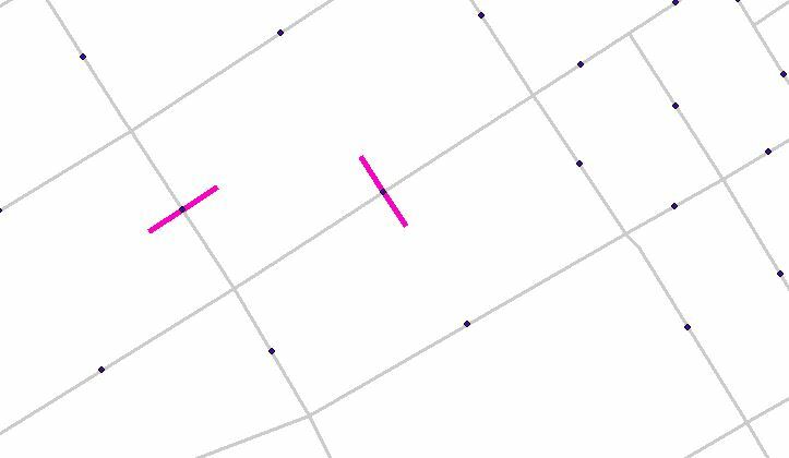
Hello! I need help creating almost the same result. I have a huge amount of lines (streets) that I need to create perpendicular lines in the middle of each one of them. In the first photo, I did it manually for the purpose of the question (pink lines).
I first tried to created points with the Snipper (distance percentage; starting location: 50; ending location : 50) where the lines should be. The points wont be use after that, it's just for reference. Is there a way that I can create line on each side of the line that is perpendicular and in the middle of it?
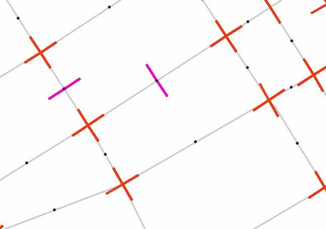
I did try the 2DVectorCalculator (Normal right and normal left) transformer, but I only get cross on the intersection. It seems that I cannot change the start and end index to move it in the middle like I want to. In the second picture, here's the result I got (red lines). I used one for normal right and another for normal left.
I'm new in FME, thanks in advance!
@jules92 Can you use the 2DVectorCaclulator form FME HUB?