What I need to do is first set the flow direction for the pipeline and from there I can use transformers to copy attributes from a point feature and copy it to the line feature that is behind it (flow direction). The line segments are not collected in a numerical object id order, so I can't figure out how to set a flow direction to be able to set attribute values that both feature classes share and should be the same.

*GDB feature classes*

Example:
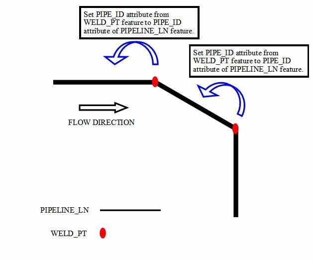
If the lines are drawn in the flow direction, then the end point can be collected by using the CoordinateExtractor using index = -1.

You can compare the X/Y with the X/Y of the Weld to get the match.


If the lines are drawn in the flow direction, then the end point can be collected by using the CoordinateExtractor using index = -1.

You can compare the X/Y with the X/Y of the Weld to get the match.


That is the problem. The lines aren't always drawn in the flow direction. Would there be any way to get around that?


You can determine the start of the line (as drawn) by using index = 0. But that will not tell you a flow direction. In your example the first line only has a weld at the end, after that weld is used the next line has two welds of which one is used by the first line etc.

But I do not know how to generate the flow direction from that information. You still need to know where to start and end. If you know that you would be able to use the ShortestPathFinder to create a path (with direction).


Hi,

Changing the direction can be done but do you have information that says which lines are present in correct or wrong direction?


I've had good experiences using the TopologyBuilder in similar cases, it will construct junction nodes and give you the attributes that indicates how the lines are connected. The junction nodes should intersect your weld points.


Reply