Hello,
I'm totally new to FME and learning from scratch and I've already did some coordinate system transformations (fomr xls to xls and dwg to dwg), but now I'm trying to transform a list of point from an excel file(name, x coordinate, y coordinate) into a dwg with a dwg template for the point name.
Now the points creation is easy but the problem is with point name that should be as a "block reference", just like the one in the template.
I'm not even sure if it DWGStyler is the right choice.
Can anyone help me out?
Thx.
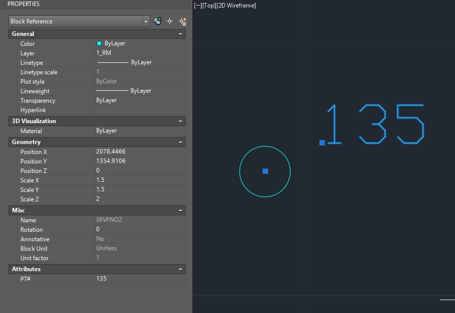
template
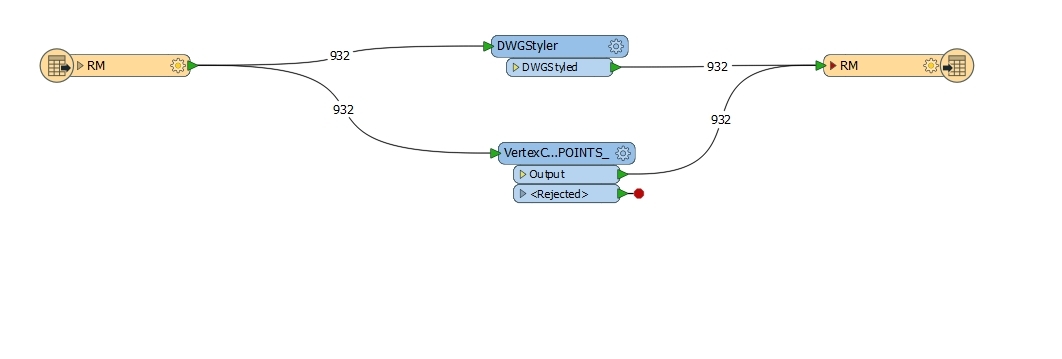
workflow