
Hereby a short description of my workflow with the questions at the end.


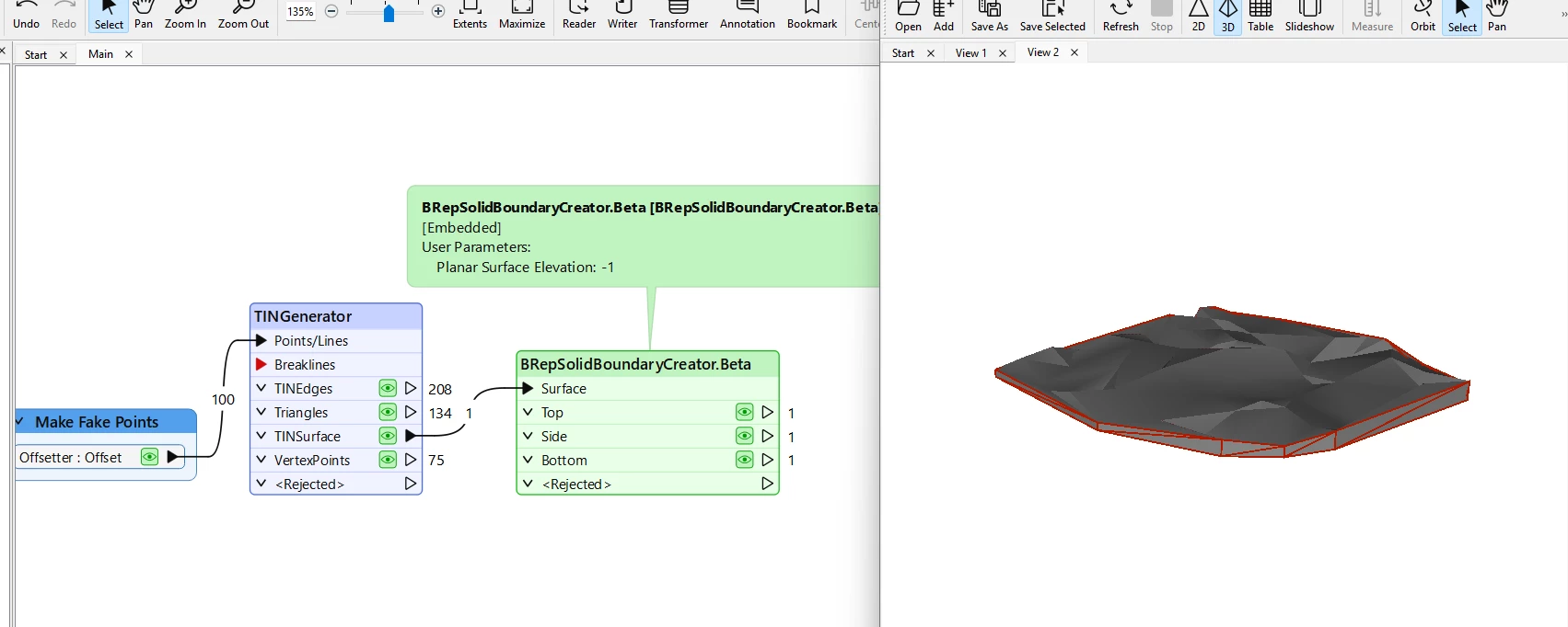
I have created a TIN from points. (TINGenerator)

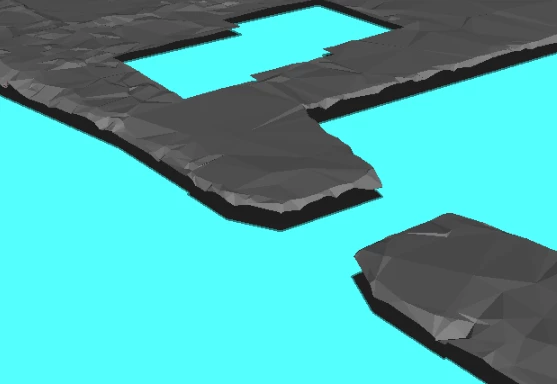
Then clipped it with polygons (water area). (Clipper)

The water polygons have been lowered to -1 meter with the 3DForcer.

With a Junction I collect both the water (3D Polygon) and the TIN (surfaces).


Here are my questions:

  1. how do I properly merge those geometrytypes together?
  2. how do I fill up the (vertical) gaps between the lower water and the surface.

I tried many transformers and different steps, but as you can guess, with no results.


Using: FME2024.1

Have you tried the “BRepSolidBoundaryCreator.Beta” Custom Transformer. 

This works pretty well - just give it the TIN and the height of the base (e.g., -1) and it should give you nice “walls".


thanks ​@virtualcitymatt for the suggestion!

It helps me to create the output the client wants… but you know me, I like to push it a little further.

So, what I actually wants is to fill the gap between the surface geometry on one hand (gray in the picture below) and the plane geometry polygons (with z-values) on the other hand (blue in the same picture).

Any ideas? 


I think in this case you would just feed in each separate TINSurface into the its own feature and then set the BRepSolidBoundaryCreator.Beta to -1. You can then just skip out the Bottom output features. 

This does assume that the “Plane” geometry with the -z values is flat