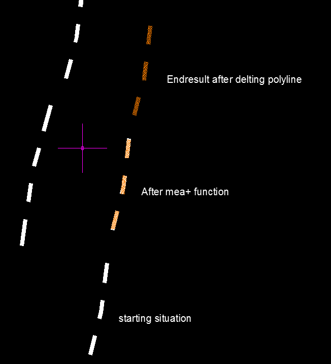
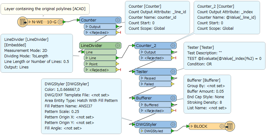
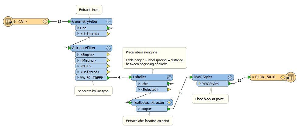
I am working on a dwg drawing containing all the traffic lines in a city and markings that are on the roads. There is a layer for each type of line or objects (Stop and yield markings for example). The problem with the DWG is that the lines are just drawn with a polyline and contain a custom linetype that gives it the look of shark's teeth but in fact are not single object. The end result should visually be the same but instead of a polyline all teeth's should be block references.
I use an free autocad pluguin mea+ to replace these lines with block references but this is quite a time consuming job in autocad.
Command: mea+
Measure with Points/Blocks/Lines/Selection ? <P>: b
Block to insert to Measure path: blok_5010
Scale for Blocks, or Graphic for symbol scaled to drawing <1>: 1
Blocks rotation, or Aligned with path or Relative angle to path [angle/A/R] <A>:
Layer for Blocks, or Current, or Same as selected path <Current>: BLOK_5010
Enter length of segment: 1
Standard measure alignment or Center on path length [S/C]? <Standard>: c
Select object to Measure:
I tried looking for a solution in FME but could not find a similar function to replace polylines into block references. Is there a workaround so i can automate this in FME?

Rename NLCS.txt to NLCS.shx and then it is possible to load in together with the dwg.


