Solved

How do I convert a .dxf file to LAS?

  • December 12, 2017
  • 4 replies
  • 305 views

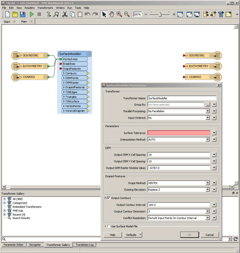
I have several .dxf files of bathymetric data that I need to convert to LAS files, they contain the following: Bathymetry (contour lines), Sounding (points), 1Xanno (points) and 0 (no idea). I am new to FME and managed to figure out how to convert .xyz files to LAS but these are a lot more complicated.

Thanks,

LG

Best answer by redgeographics

You could do that by using a SurfaceModeller. Feed the bathymetry and soundings in there (assuming these are respectively 3d lines and points) and then take the DEM points output (setting the DEM spacing to an appropriate size) and feed those into a LAS writer.

View original
Did this help you find an answer to your question?

4 replies

redgeographics
Celebrity
Forum|alt.badge.img+49
  • Celebrity
  • Best Answer
  • December 12, 2017

You could do that by using a SurfaceModeller. Feed the bathymetry and soundings in there (assuming these are respectively 3d lines and points) and then take the DEM points output (setting the DEM spacing to an appropriate size) and feed those into a LAS writer.


  • Author
  • December 12, 2017
redgeographics wrote:

You could do that by using a SurfaceModeller. Feed the bathymetry and soundings in there (assuming these are respectively 3d lines and points) and then take the DEM points output (setting the DEM spacing to an appropriate size) and feed those into a LAS writer.

Thanks for your reply! Unfortunately I still have no idea what to do with this. I will read up on the SurfaceModeller transformer but if you have time to explain this further, that would be great!

redgeographics
Celebrity
Forum|alt.badge.img+49
lgrant wrote:

Thanks for your reply! Unfortunately I still have no idea what to do with this. I will read up on the SurfaceModeller transformer but if you have time to explain this further, that would be great!
The Surface Tolerance is a filtering value. If you set it to 0 all input features will be considered for generating the surface, any positive value will filter out features. From the docs:


When a positive value for surface tolerance is specified, it works as follows. For each vertex that is being added to the model:


  • If the x,y location is outside the 2D convex hull of the existing surface model, it is added to the model.
  • If the x,y location is inside the 2D convex hull of the existing surface model:
    • The difference between the z value from the existing surface model and the z value of the vertex is calculated.
    • This difference is compared to the surface model tolerance.
    • The vertex is only added to the surface model if the difference is greater than the surface tolerance; otherwise, the vertex is discarded.
The other parameter that's important to you right now is the output DEM spacing, X and Y. That will determine the point density of the DEM you're eventually going to write to the LAS. Lower values = higher density (not necessarily accuracy)


You'll have to experiment with these values a bit and see what output works best for you. Keep in mind it's interpolating from your source data so what I would try first is set the surface tolerance to 0 and the DEM spacing to a value that's similar to the (average) spacing of your soundings.


redgeographics
Celebrity
Forum|alt.badge.img+49
redgeographics wrote:
The Surface Tolerance is a filtering value. If you set it to 0 all input features will be considered for generating the surface, any positive value will filter out features. From the docs:


When a positive value for surface tolerance is specified, it works as follows. For each vertex that is being added to the model:


  • If the x,y location is outside the 2D convex hull of the existing surface model, it is added to the model.
  • If the x,y location is inside the 2D convex hull of the existing surface model:
    • The difference between the z value from the existing surface model and the z value of the vertex is calculated.
    • This difference is compared to the surface model tolerance.
    • The vertex is only added to the surface model if the difference is greater than the surface tolerance; otherwise, the vertex is discarded.
The other parameter that's important to you right now is the output DEM spacing, X and Y. That will determine the point density of the DEM you're eventually going to write to the LAS. Lower values = higher density (not necessarily accuracy)


You'll have to experiment with these values a bit and see what output works best for you. Keep in mind it's interpolating from your source data so what I would try first is set the surface tolerance to 0 and the DEM spacing to a value that's similar to the (average) spacing of your soundings.


Also, inspect your source data! The bathymetry should be 3d lines and the soundings should be 3d points. Use a 3DForcer if they're not.


Reply


Cookie policy

We use cookies to enhance and personalize your experience. If you accept you agree to our full cookie policy. Learn more about our cookies.

 
Cookie settings