Hi,
Â
Â
Â
If you use dwg Styler and select a fill patern, these will be hatches. Solid colour you would select solid hatch.
Â
Â
You must then select Area Entitiy Type = Hatch With Fill Pattern.
Â
Then it will show the colours you chose. It will automaticaly override the default color.
Â
Â
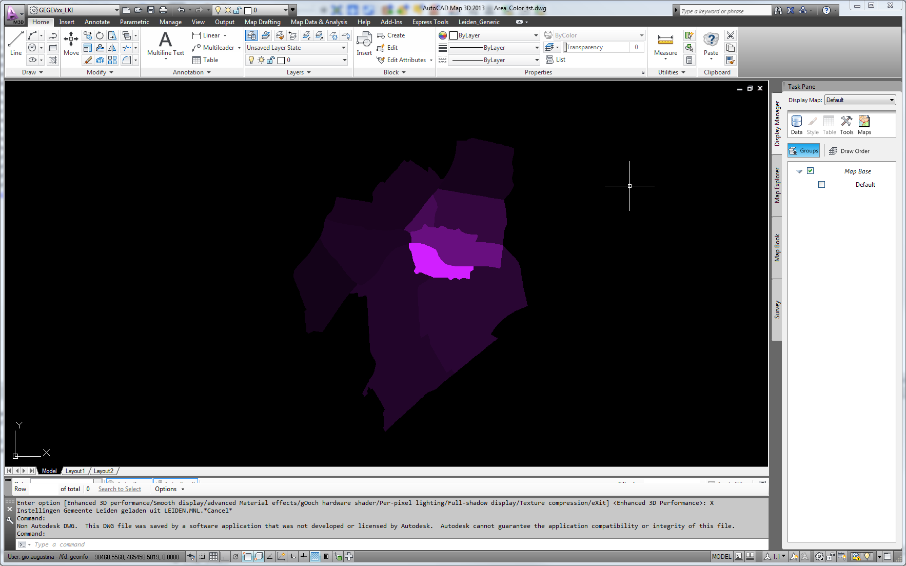
This
Â
@Evaluate(1/(@Value(WIJKCODE)*1.0+1)*0.823529),@Evaluate(1/(@Value(WIJKCODE)*1.0+1)*0.12549),@Evaluate(1/(@Value(WIJKCODE)*1.0+1)*1)
Â
yields this dwg
Â
Â
Â
Â
Â
Â
btw the fme transformers accept color in  r,b,g as 0-1. As in the expression above.
Hmmm....
i don't understand completely.....now i have set an index for the color and write it in the attribute autocad_color......so i can get the borderline......and the fill?...is there any format attribute i have to place the index for the color or it is enough to set the right Area Entity type?
Â
Â
Greetz
Â
Franco
Hi Franco,
Â
Â
You can set an attribute which stores color value to the "Color" parameter of the DWGStyler. But, note that the color value should be comma-separated normalized RGB component values.
Â
For example, the color value of Autocad Color Index "30" (R=255, G=127, B=0) will be "1,0.498039,0" (i.e. 255/255, 127/255, 0/255).
Â
So, if you need to set a color equivalent to an Autocad Color Index, you may have to convert the index to a color value.
Â
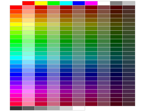
I found a web page containing a table of Autocad Color Index and RGB values.
Â
AutoCAD Color Index (ACI) RGB equivalents (
http://www.isctex.com/acadcolors.php)
Â
Â
Takashi
yes, format of color is like fme writes them.
Â
If u use a colorsetter and clikc a color you see the format.
Â
 i.e. r,g,b=0.2,0.3,0.45 etc.
Â
You can use a creator to calculate and format the string (as in my example).
Â
Â
You don't need to set any format attribute after the styler to get the dwg writer to create it.
Â
Â
Â
my example create a color graduation (based on r= 0.823529, g= 0.12549, b=1) A purple gradient...
I managed to add SummaryInfo Comments (also known as DWG properties) to DWG files (created by FME Desktop) using ObjectDBX in a Windows Powershell  post process and wonder if it is possible to do it directly in FME Desktop:
$srcDir = "C:\DWG\infiles\"
$tgtDir = "C:\DWG\outfiles\"
$errorFile = 'C:\DWG\error.log'
$comments = 'C:\DWG\comments.csv'
Â
$AutoCad = New-Object -ComObject Autocad.Application
$AcadVer = $AutoCad.ActiveDocument.GetVariable("ACADVER")
$AcadVer = $AcadVer.Split(".")a0]
$DbxId = "ObjectDBX.AXDbDocument."+$AcadVer
$Dbx = $AutoCAD.GetInterfaceObject($DbxId)
Â
foreach($line in Get-Content $comments -Encoding UTF8)
{
  $data = $line.Split(";")
  Write-Host $dataF0]
  try{
    $Dbx.Open($srcDir+$datar0]+".dwg")
    $Dbx.SummaryInfo.Comments = $dataÂ1]
    $Dbx.SaveAs($tgtDir+$datar0]+".dwg")
  }
  catch{
    $error_msg = $srcDir+$dataa0]+".dwg"
    Out-File -FilePath $errorFile -Append -InputObject $error_msg
Write-Host "Error: ",$data>0]
  }
}
comments.csv:
4233-15_1;Last Change - VA40:21.10.2020
4234-31_3;Last Change - VA40:21.10.2020
4234-31_4;Last Change - VA40:21.10.2020
4234-32_1;Last Change - VA40:21.10.2020
As a workaround/hack in FME Workspace, I added a temporary DXF header with the included comments to my DWG Writer , but unfortunately this only works with "AutoCAD DWG Writer" and not with "RealDWG Writer" anymore (FME Desktop 2020.2 Windows 10/64bit).
Â
2 years ago I had no problems adding DXF headers to DWG files using RealDWG, but the current FME version can't add these headers with the REAL driver. I really need the RealDWG Writer to prevent these annoying TrustedDWG messages Â
Â
and for completeness...here is a link where an excel file with autocad color index and RGB numbers is downloadable!
Â
Â
https://onedrive.live.com/view.aspx?resid=CB948AEB4728C76D!1356&app=Excel&authkey=!AGqmRz6KTXsCdWgÂ
Â
Greetz
Â
Franco
Additional Question......now i have all areas in right color....but when all areas should have a black borderline...can i only solve this when i write the borderline as lines also?...but then i have double data....another solution?
Thx
Franco
As far as I know, there is no way to set border color of hatch entity independently from setting fill color. I think you will have to create another set of polygon or line features to draw borders.
Â
Â
Thanks for sharing the Excel table. As an example for calculating color values, I created a workspace which reads your table. (
https://drive.google.com/file/d/0B0ufVP2t0eApZ0ttVzZ4d194dzA/view?usp=sharing)
Â
Perfect!!!
Thank you very much!!!