Solved

DWG Units


deanhowell
Influencer
Forum|alt.badge.img+23

Hello all,

I am trying to validate DWG files and that they have been drawn using metric units.

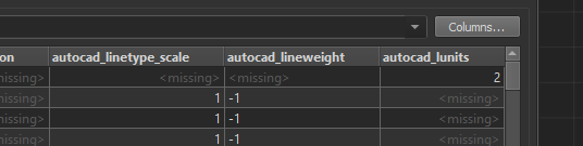
I have exposed the 'Read Drawing System Variables' and that gives me access to autocad_lunits but I am trying to figure out what the output means.

In the image below the autocad_lunits comes back with a value of 2 on the 0 layer but not sure what 2 really means.

Does anyone know what the range of options that AutoCAD produce or if there is another way to find what units are being used in the drawing?


Note: I know this particular drawing is in metric units but not sure what other values could be expected.

Best answer by becchr

hi @deanhowell, also the INSUNITS system variable might be interesting to check:

ACAD

FME

View original
Did this help you find an answer to your question?

4 replies

virtualcitymatt
Celebrity
Forum|alt.badge.img+35

becchr
Influencer
Forum|alt.badge.img+25
  • Influencer
  • Best Answer
  • April 2, 2020

hi @deanhowell, also the INSUNITS system variable might be interesting to check:

ACAD

FME


deanhowell
Influencer
Forum|alt.badge.img+23
  • Author
  • Influencer
  • April 2, 2020
becchr wrote:

hi @deanhowell, also the INSUNITS system variable might be interesting to check:

ACAD

FME

Thanks @becchr I think it will be a combination of this and lunits as at the end of the day I am trying to make sure the drawing has been drawn in meters.


deanhowell
Influencer
Forum|alt.badge.img+23
  • Author
  • Influencer
  • April 2, 2020

Reply


Cookie policy

We use cookies to enhance and personalize your experience. If you accept you agree to our full cookie policy. Learn more about our cookies.

 
Cookie settings