Hi,


I am a beginner in FME and have very limited knowledge of it. I would like to join a polygon shape file, with an Excel spreadsheet that shares a common ID , then convert the joined file to DGN.


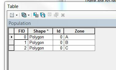
My shape file looks like this :
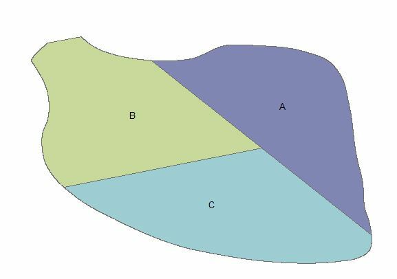


The attribute table:


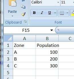
Spreadsheet:


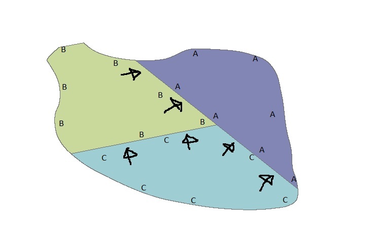
For the result, I would like to have the DGN showing arrow heads along the polygons, pointing to the area with the lower population:
 

This is getting way harder that I thought it would be. Would someone help me please? Any suggestion will be greatly appreciated! Thank you so much!!!!
Hi,


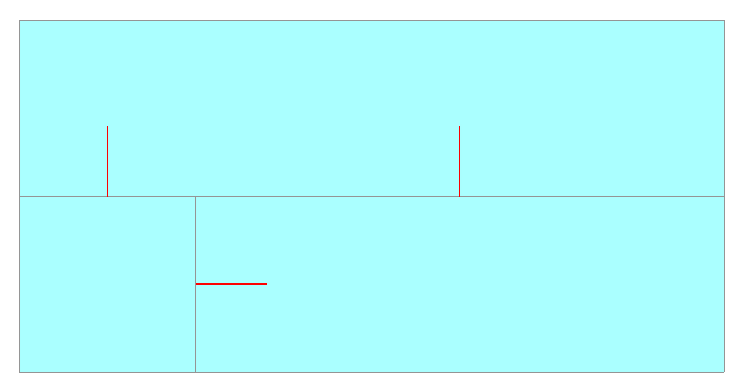
I tried creation of lines which orient to neighbor polygons having less population from a polygon having greater population. Red lines in this image are the result.


The result was generated by the following procedure. It might become a prototype for your solution.


Assume that the source polygons are topologically clean.


Step 1


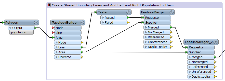
1) Send all the polygons to a ToplogyBuilder. The transformer adds "_arc_id", "_left_polygon", "_right_polygon" to the output lines, and adds "_polygon_id" to the output areas. The following processes will use those attributes.


2) Select shared boundary lines by the Tester.


0 < _left_polygon AND 0 < _right_polygon


3) Merge population of left side polygon to each boundary line (FeatureMerger).


Join On: "_left_polygon" to "_polygon_id"


Supplier Prefix: left_


4) Merge population of right side polygon to each boundary line (FeatureMerger_2).


Join On: "_right_polygon" to "_polygon_id"


Supplier Prefix: right_"


Step 2


5) Determine which side has greater population (Tester_2).


left_population < right_population


6) Reverse orientation of the Passed lines, so that the left population is greater (Orientor).


7) Send all the lines to the AttributeCreator to create an attribute named "_point_order".


_point_order = 1


8) On the other hand, send all the lines to the OffsetCurveGenerator to create left hand side offset lines.


Offset: <length of required line>


9) Connect another AttributeCreator to the OffsetCurveGenerator.


_point_order = 0


The start points of finally resulting lines will be on the offset lines, and the end points will be on the boundary lines. The "_point_order" will be used to determine direction of the lines in the Step 3.


10) Send all the lines to the Snipper to transform them into points. The points will be start and end nodes of the resulting lines. For example, the Snipper with this setting transforms input lines into their middle points.


Snipping Mode: Distance (Percentage)


Starting Location: 50


Ending Location: 50


Step 3


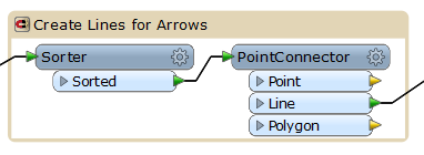
11) Sort the points by "_arc_id" and "_point_order". "_arc_id" was added by the TopologyBuilder. 


12) Connect points to create line segments by the PointConnector.


Connection Break Attributes: _arc_id


Sorry, I don't know how to save the resulting lines as arrows into DGN format dataset.


Hope somebody helps to do that.


Takashi
The first Tester (Step 1) may not be essential since the following two FeatureMergers will filter out non-shared boundary lines.
Thank you so much Takashi! Thank you for your prompt reply! I will try this with my coworker tomorrow (Today is Rememberance Day in Canada). I really appreciate it! if i run into any problem ( probably will), I will post it here. Thank you!!!!
I updated the prototype so that the number of arrow lines for each boundary will be calculated automatically. Download the workspace example from here. (https://drive.google.com/file/d/0B0ufVP2t0eApV2ZRQmR5NHUyWDg/view?usp=sharing)
This version uses another approach to create required lines. (https://drive.google.com/file/d/0B0ufVP2t0eApdGpoSlR1RnBxZVE/view?usp=sharing)
Thank you so much Takashi!!! I just downloaded them and will try them out today.

Reply