Question

Automate the creation of 3D planar surface


3d_ff
Contributor
Forum|alt.badge.img+5
  • Contributor

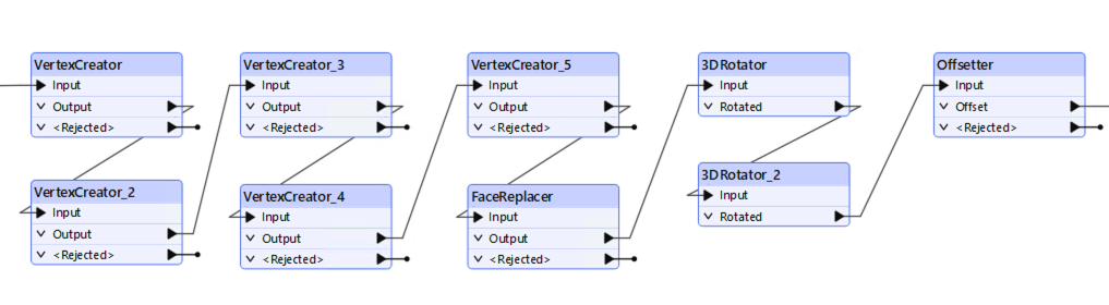
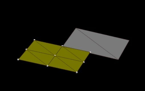
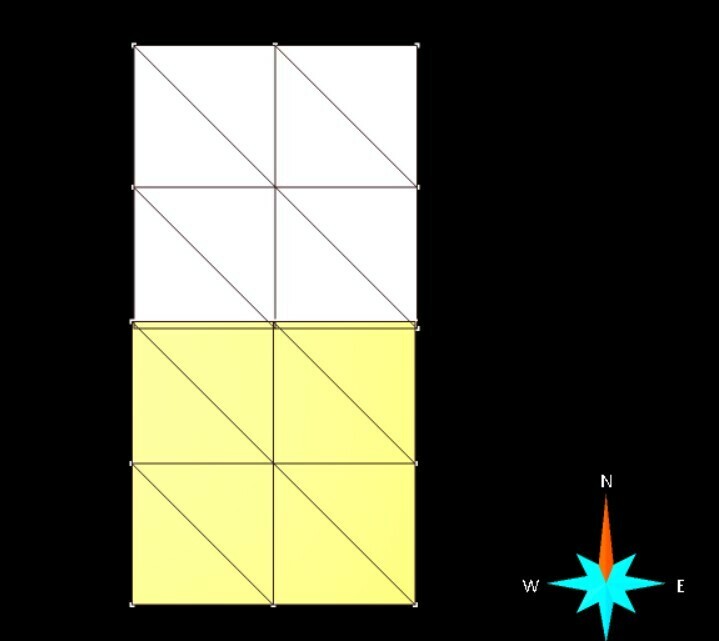
Is there a way through FME to automate the creation of plates (3D planar surface), from the following data:

  • XYZ position (centroid)
  • Shape: Always has 4 sides but not necessarily always a rectangle
  • Dimensions info: Width and Length
  • Orientation info: Azimut (DipDIR) and DIP

6 replies

daveatsafe
Safer
Forum|alt.badge.img+19
  • Safer
  • March 25, 2025

Hi ​@3d_ff,

Please try the following process:

  • Use VertexCreators to create the polygon, using X and Y values relative to the centroid at 0,0, based on the width and height
  • Use the FaceReplacer to create a face from the polygon
  • Use a 3DRotator to rotate to the DIP angle around the Y axis
  • Use a 3DRotator to rotate to the Azimuth around the Z axis
  • Use an Offsetter to move the face centroid to its XYZ location


3d_ff
Contributor
Forum|alt.badge.img+5
  • Author
  • Contributor
  • March 26, 2025

@daveatsafe 

Thank you for your prompt and detailed response. We are thrilled to be close to our end goal and appreciate your suggested process for automating the 3D planar surfaces creation with FME.

We tried it out with an extra detail, i.e. forcing the left-hand corner to be the object’s origin, by adding a start_x and start_y in the CSV file. Within our CSV test file, we have three different objects to build with unique-IDs identifying them. So, when we set up the transformations, the three objects are created, and their dimensions are correct.

However, unfortunately, it seems that FME currently treats all three objects as related, resulting in the dip and azimuth being applied correctly to only one object. We need to ensure that the transformation understands that each object should be processed independently, using the information from the CSV file.

Specifically, we require the following:

  • Unique ID Assignment: Each 3D surface must be assigned its unique ID from the CSV.
  • Independent Rotation (Dip): Each object should be rotated along the Y-axis according to its unique dip value from the CSV.
  • Independent Rotation (Azimuth): Each object should be rotated around the Z-axis according to its unique azimuth value from the CSV.
  • Independent Centroid Offset: Each object should be moved to its unique XYZ centroid location from the CSV.

We need to process hundreds of objects daily and maintain their accuracy, so ensuring each object is handled independently is crucial.

With our first result feedback from our testing the FME transformations mentioned above, we now understand that the coordinates in the spreadsheet, previously assumed to be centroids, actually represent the top center of the planar surface.

We are aiming to achieve the yellow result in our image, while our initial test resulted in the grey output.

To reiterate, we are currently using FME transformations with:

  • Y-axis for dip rotation.
  • Z-axis for azimuth rotation.
  • Accurate size definition by setting the bottom-left corner as the origin (0,0) and using width and height to define the other three corners' local X and Y coordinates.

The remaining challenge is to correctly position the planar surface in 3D space using the XYZ coordinates from the CSV table, considering the top center as the reference point.

To summarize the refined requirements:

  1. Independent Object Processing: Each object must be processed independently using its unique ID and corresponding attributes from the CSV.
  2. Accurate Rotation: Dip rotation around the Y-axis and azimuth rotation around the Z-axis should be applied correctly to each object.

Top Center Positioning: The XYZ coordinates in the CSV table represent the top center of the planar surface, and the object needs to be positioned accordingly.

So, ​​instead of creating a local centroid point, it will be necessary to automate the creation of the local TOP_Center coordinates, to then use within the last step; i.e. the offset of the TOP_Center_local coordinates offsetted to the TOP_Center_XYZ coordinates within the CSV file.

Could you please provide guidance on how to implement this adjustment in FME, specifically how to calculate the offset to position the top center correctly? We are particularly interested in any FME transformers or techniques that can facilitate this calculation.

We are confident that with this final adjustment, we can achieve the desired results and efficiently process our daily updates.


daveatsafe
Safer
Forum|alt.badge.img+19
  • Safer
  • March 26, 2025

Hi ​@3d_ff,

Could you share a copy of your CSV file? It would be helpful to know what the starting point of the automation is.


3d_ff
Contributor
Forum|alt.badge.img+5
  • Author
  • Contributor
  • March 26, 2025

Here are the files for our first tests


daveatsafe
Safer
Forum|alt.badge.img+19
  • Safer
  • March 26, 2025

Hi ​@3d_ff,

Please try the attached workspace.


3d_ff
Contributor
Forum|alt.badge.img+5
  • Author
  • Contributor
  • March 29, 2025

We tested the last suggested workflow for building the surfaces. The results are promising; the plate (grey) is now positioned correctly in the X (easting) and Z (elevation) directions, as shown in the image (yellow is the goal).


However, we've observed that the Y (northing) position seems to be doubled.

Additionally, we need clarification on FME's dip and azimuth convention. Specifically:

  • Why was the dip applied to the X-axis instead of the Y-axis, as previously discussed?
  • Why were negative values applied to both the dip and azimuth?

We are attaching the workflow we tested this past Friday afternoon for your review.

Thank you for your assistance.


Reply


Cookie policy

We use cookies to enhance and personalize your experience. If you accept you agree to our full cookie policy. Learn more about our cookies.

 
Cookie settings