Solved

How To Create Parallel Lines And Parallel Vertices


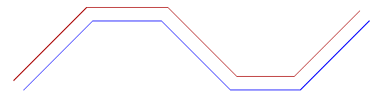
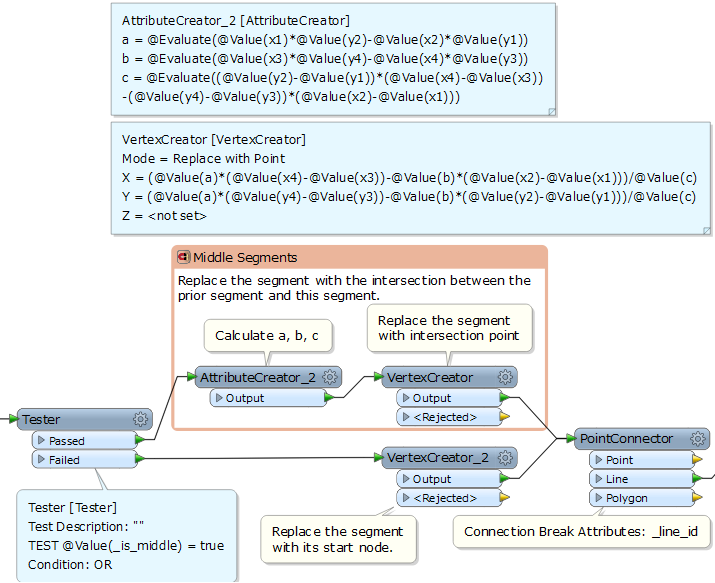
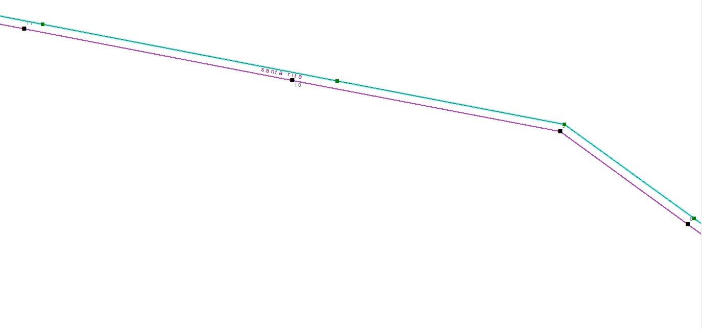
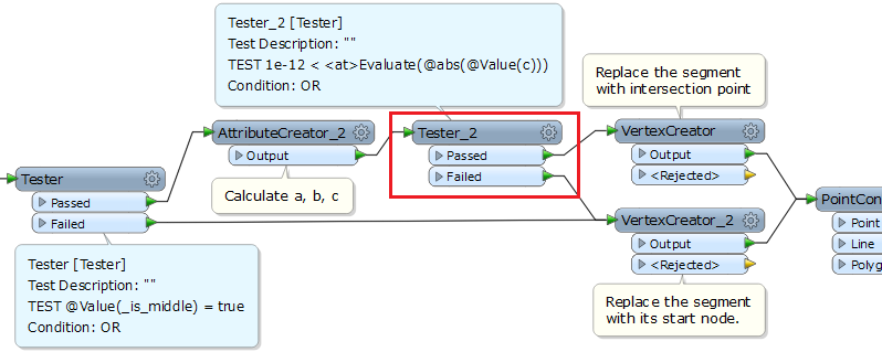
I am trying to create two offset lines from the original line that will be parallel and have parallel vertices from beginning to end. The Offsetter does not do this nor does the OffsetCurveGenerator, AnchoredSnapper combination do this. If I can't figure out how to do this in FME then I will perform this in Oracle Spatial. Here are the steps I will take in that case:

1.) Generate segmented lines from the original line split at each vertex point.

2.) Determine the line direction (angle) of every segment.

3.) Rotate each segment 90 degrees from each forward vertex.

4.) Extend each rotated segment so that they are long enough to apply vertices at offset distance on each side of original line..

5.) Add vertices on both sides of rotated segments at the offset distance for each side.

6.) Connect the vertices on each side of the original line to create two new parallel lines.

If there is a way to do this in FME that I have not figured out, please let me know.

Thanks

Dan

Best answer by takashi

Hi @dastucky, summary of my idea is:

  • decompose the original line into individual segments
  • move the segments parallel
  • compute intersection between two straight lines (extensions of two adjoining segments)
  • connect the intersections to create required line

The intersection (x, y) of two straight lines can be calculated mathematically.

Line 1: (x1, y1) - (x2, y2), Line 2: (x3, y3) - (x4, y4)

Note: Line 1 is not parallel to Line 2.

a = x1 * y2 - x2 * y1

b = x3 * y4 - x4 * y3

c = (y2 - y1) * (x4 - x3) - (y4 - y3) * (x2 - x1)

x = {a * (x4 - x3) - b * (x2 - x1)} / c

y = {a * (y4 - y3) - b * (y2 - y1)} / c

Actual data flow would be a little bit complicated. See the attached example: create-parallel-line-prototype.fmw

Result:

Hope this helps.

View original
Did this help you find an answer to your question?

12 replies

erik_jan
Contributor
Forum|alt.badge.img+17
  • Contributor
  • March 8, 2016

What is wrong with the OffsetCurveGenerator? That seems to do exactly what you describe.


  • Author
  • March 8, 2016
erik_jan wrote:

What is wrong with the OffsetCurveGenerator? That seems to do exactly what you describe.

The OffsetCurveGenerator creates a curve (with multiple vertices) where the original line is angular with a single vertex. It's not a parallel line as it has a different shape. There also isn't a 1 to 1 relationship with the vertices in the original line with the offset lines if created by the Off

setCurveGenerator.

takashi
Influencer
  • Best Answer
  • March 9, 2016

Hi @dastucky, summary of my idea is:

  • decompose the original line into individual segments
  • move the segments parallel
  • compute intersection between two straight lines (extensions of two adjoining segments)
  • connect the intersections to create required line

The intersection (x, y) of two straight lines can be calculated mathematically.

Line 1: (x1, y1) - (x2, y2), Line 2: (x3, y3) - (x4, y4)

Note: Line 1 is not parallel to Line 2.

a = x1 * y2 - x2 * y1

b = x3 * y4 - x4 * y3

c = (y2 - y1) * (x4 - x3) - (y4 - y3) * (x2 - x1)

x = {a * (x4 - x3) - b * (x2 - x1)} / c

y = {a * (y4 - y3) - b * (y2 - y1)} / c

Actual data flow would be a little bit complicated. See the attached example: create-parallel-line-prototype.fmw

Result:

Hope this helps.


  • Author
  • March 9, 2016
takashi wrote:

Hi @dastucky, summary of my idea is:

  • decompose the original line into individual segments
  • move the segments parallel
  • compute intersection between two straight lines (extensions of two adjoining segments)
  • connect the intersections to create required line

The intersection (x, y) of two straight lines can be calculated mathematically.

Line 1: (x1, y1) - (x2, y2), Line 2: (x3, y3) - (x4, y4)

Note: Line 1 is not parallel to Line 2.

a = x1 * y2 - x2 * y1

b = x3 * y4 - x4 * y3

c = (y2 - y1) * (x4 - x3) - (y4 - y3) * (x2 - x1)

x = {a * (x4 - x3) - b * (x2 - x1)} / c

y = {a * (y4 - y3) - b * (y2 - y1)} / c

Actual data flow would be a little bit complicated. See the attached example: create-parallel-line-prototype.fmw

Result:

Hope this helps.

Thank you very much. Can you provide a screenshot of your workspace? I'm using ESRI Interoperability which doesn't import fmw files as far as I know.


takashi
Influencer
  • March 9, 2016
takashi wrote:

Hi @dastucky, summary of my idea is:

  • decompose the original line into individual segments
  • move the segments parallel
  • compute intersection between two straight lines (extensions of two adjoining segments)
  • connect the intersections to create required line

The intersection (x, y) of two straight lines can be calculated mathematically.

Line 1: (x1, y1) - (x2, y2), Line 2: (x3, y3) - (x4, y4)

Note: Line 1 is not parallel to Line 2.

a = x1 * y2 - x2 * y1

b = x3 * y4 - x4 * y3

c = (y2 - y1) * (x4 - x3) - (y4 - y3) * (x2 - x1)

x = {a * (x4 - x3) - b * (x2 - x1)} / c

y = {a * (y4 - y3) - b * (y2 - y1)} / c

Actual data flow would be a little bit complicated. See the attached example: create-parallel-line-prototype.fmw

Result:

Hope this helps.

Hi @dastucky, see these images.

Part 1

Part 2

Part 3


gio
Contributor
Forum|alt.badge.img+15
  • Contributor
  • March 9, 2016

this is also in an old post, about zero stroke offsetter...

heres an old pic (sep 2014)


  • Author
  • March 9, 2016
takashi wrote:

Hi @dastucky, see these images.

Part 1

Part 2

Part 3

Thanks @takashi for your help. The lines look good after the implementation however I noticed that the vertices in the new line don't always line up with the vertices in the original line. For the purposes of my work, I need to have that as well in the solution I use. Is there something that can be adjusted/added to allow for this? I've attached a pic to demonstrate what I mean. The corners vertices line up well however it's the ones usually on straight lines that are off at times.


takashi
Influencer
  • March 10, 2016
takashi wrote:

Hi @dastucky, summary of my idea is:

  • decompose the original line into individual segments
  • move the segments parallel
  • compute intersection between two straight lines (extensions of two adjoining segments)
  • connect the intersections to create required line

The intersection (x, y) of two straight lines can be calculated mathematically.

Line 1: (x1, y1) - (x2, y2), Line 2: (x3, y3) - (x4, y4)

Note: Line 1 is not parallel to Line 2.

a = x1 * y2 - x2 * y1

b = x3 * y4 - x4 * y3

c = (y2 - y1) * (x4 - x3) - (y4 - y3) * (x2 - x1)

x = {a * (x4 - x3) - b * (x2 - x1)} / c

y = {a * (y4 - y3) - b * (y2 - y1)} / c

Actual data flow would be a little bit complicated. See the attached example: create-parallel-line-prototype.fmw

Result:

Hope this helps.

@dastucky, when adjoining two segments are on a straight line (the vertex between them is on the straight line), "c" will be zero and the intersection won't be computed correctly. Try inserting another Tester to filter the parallel segments according to the value of "c" (whether it is near equal to zero)..


takashi
Influencer
  • March 10, 2016

Hi @dastucky, I confirmed that a small Python script can perform the same manipulation. This script may also be helpful if Esri Data Interop. supports the PythonCaller.

# PythonCaller Script Example:  Offset Line
# Offset direction is determined by the sign of specified offset amount:
# Positive amount makes LEFT offset; Negative amount makes RIGHT offset.
# The offset line always will be created in 2D even if the original line is in 3D.
# Assume that the input feature has a single Line geometry,
# and the original line has no duplicate coordinates, no dangles.
# Note: Depending on the shape of the original line and the offset amount,
# there are cases where the resulting line has self-intersections. The shape of
# resulting line may not be preferable if self-intersections have occurred.

import fmeobjects, math

def offsetLine(feature):
    # Get all coordinates of the original line.
    coords = feature.getAllCoordinates()
    
    # Get offset amount from a feature attribute called "_offset".
    # Modify the attribute name if necessary.
    offset = float(feature.getAttribute('_offset'))
    
    # Calculate start and end coordinates of every parallel segment.
    segments = []
    for i in range(len(coords) - 1):
        x1, y1, x2, y2 = coords[i][0], coords[i][1], coords[i+1][0], coords[i+1][1]
        r = offset / math.hypot(x2 - x1, y2 - y1)
        vx, vy = (x2 - x1) * r, (y2 - y1) * r
        segments.append(((x1 - vy, y1 + vx), (x2 - vy, y2 + vx)))
            
    # Function that returns the intersection (x, y) of two lines.
    def intersection(((x1, y1), (x2, y2)), ((x3, y3), (x4, y4))):
        dx1, dy1, dx2, dy2 = x2 - x1, y2 - y1, x4 - x3, y4 - y3
        a, b, c = x1 * y2 - x2 * y1, x3 * y4 - x4 * y3, dy1 * dx2 - dy2 * dx1
        return ((a * dx2 - b * dx1) / c, (a * dy2 - b * dy1) / c) if 1e-12 < abs(c) else (x2, y2)
        
    # Set the resultant offset line to the input feature.
    feature.setGeometry(fmeobjects.FMELine([segments[0][0]] \
        + [intersection(s, t) for s, t in zip(segments[:-1], segments[1:])] \
        + [segments[-1][1]]))

  • Author
  • March 10, 2016
takashi wrote:

Hi @dastucky, I confirmed that a small Python script can perform the same manipulation. This script may also be helpful if Esri Data Interop. supports the PythonCaller.

# PythonCaller Script Example:  Offset Line
# Offset direction is determined by the sign of specified offset amount:
# Positive amount makes LEFT offset; Negative amount makes RIGHT offset.
# The offset line always will be created in 2D even if the original line is in 3D.
# Assume that the input feature has a single Line geometry,
# and the original line has no duplicate coordinates, no dangles.
# Note: Depending on the shape of the original line and the offset amount,
# there are cases where the resulting line has self-intersections. The shape of
# resulting line may not be preferable if self-intersections have occurred.

import fmeobjects, math

def offsetLine(feature):
    # Get all coordinates of the original line.
    coords = feature.getAllCoordinates()
    
    # Get offset amount from a feature attribute called "_offset".
    # Modify the attribute name if necessary.
    offset = float(feature.getAttribute('_offset'))
    
    # Calculate start and end coordinates of every parallel segment.
    segments = []
    for i in range(len(coords) - 1):
        x1, y1, x2, y2 = coords[i][0], coords[i][1], coords[i+1][0], coords[i+1][1]
        r = offset / math.hypot(x2 - x1, y2 - y1)
        vx, vy = (x2 - x1) * r, (y2 - y1) * r
        segments.append(((x1 - vy, y1 + vx), (x2 - vy, y2 + vx)))
            
    # Function that returns the intersection (x, y) of two lines.
    def intersection(((x1, y1), (x2, y2)), ((x3, y3), (x4, y4))):
        dx1, dy1, dx2, dy2 = x2 - x1, y2 - y1, x4 - x3, y4 - y3
        a, b, c = x1 * y2 - x2 * y1, x3 * y4 - x4 * y3, dy1 * dx2 - dy2 * dx1
        return ((a * dx2 - b * dx1) / c, (a * dy2 - b * dy1) / c) if 1e-12 < abs(c) else (x2, y2)
        
    # Set the resultant offset line to the input feature.
    feature.setGeometry(fmeobjects.FMELine([segments[0][0]] \
        + [intersection(s, t) for s, t in zip(segments[:-1], segments[1:])] \
        + [segments[-1][1]]))

Hi @takashi.  I was able to get it to work in FME correctly last night with parallel vertices and parallel lines.  I had to play around with the "c" value to get it to provide the perfect results.  Thanks again for your help.  Also, thanks for the python script info as well!!!  I appreciate your help with this!!


gio
Contributor
Forum|alt.badge.img+15
  • Contributor
  • March 10, 2016

all of this was also created in this thread

https://knowledge.safe.com/questions/3174/parallel...

and a follow up


mark2atsafe
Safer
Forum|alt.badge.img+44
  • Safer
  • March 10, 2016
dastucky wrote:

The OffsetCurveGenerator creates a curve (with multiple vertices) where the original line is angular with a single vertex. It's not a parallel line as it has a different shape. There also isn't a 1 to 1 relationship with the vertices in the original line with the offset lines if created by the Off

setCurveGenerator.

Yeah, when the angle parameter is set to 90 you would expect a single angular point. That's already filed with our developers and I added this thread to see if we can increase the priority.


Cookie policy

We use cookies to enhance and personalize your experience. If you accept you agree to our full cookie policy. Learn more about our cookies.

 
Cookie settings