Question

remove side contours from clipped Surface


Forum|alt.badge.img

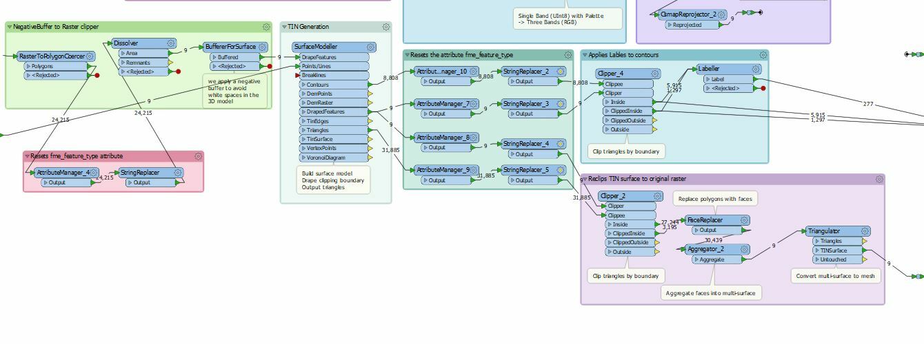
I am using surfaceModeller to generate TIN surfaces, I need them to be stacked as they represent various height and they have to be like that.


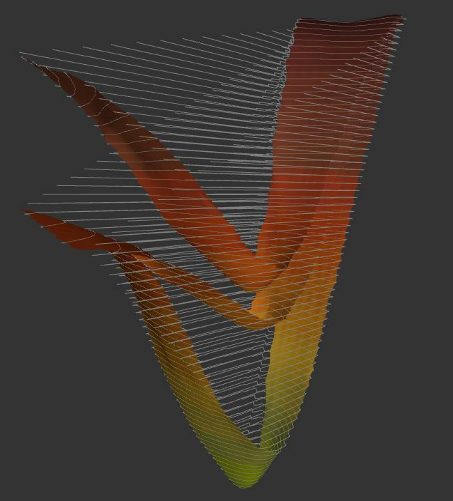
Triangulation and draping work ok, the only thing I would like to remove are the contours on the side.

See image of the pdf as example of output. I already tried a negative buffer but it does not work as it removes also some internal contours that I would like to keep.

Could anyone help?


4 replies

daveatsafe
Safer
Forum|alt.badge.img+19
  • Safer
  • March 21, 2019

Hi @alex_chris,

You can use a Clipper transformer to trim the side contours. To generate, the clip boundary, please try a HullReplacer transformer on the source points, then a Bufferer to shrink the hull polygon slightly inside the points. You seem to have three point sets in your source - I would recommend doing the process separately for each set.


itay
Supporter
Forum|alt.badge.img+16
  • Supporter
  • March 21, 2019

Don't know what I am exactly looking at but it looks very artistic! FME Art?


Forum|alt.badge.img
  • Author
  • March 22, 2019
daveatsafe wrote:

Hi @alex_chris,

You can use a Clipper transformer to trim the side contours. To generate, the clip boundary, please try a HullReplacer transformer on the source points, then a Bufferer to shrink the hull polygon slightly inside the points. You seem to have three point sets in your source - I would recommend doing the process separately for each set.

Hi @daveatsafe, thanks for your response. I managed to get the side contours out of the way. I replaced TIN Generator with Surface modeller, and before sending the raster to become TIN I clip with a slightly negative buffer the clipper, and submit it to the SurfaceModeller in the drapeFeatures port. After that, I get the outputs from the SurfaceModeller separately (Triangles, Draped features) and I clip them again, using the draped features as clippers and the triangles as clippee. 

It was inspired by this article.

https://knowledge.safe.com/articles/1310/how-to-clip-tin-surfaces.html

Here is a screenshot of the detail of the workflow (The attribute managers are there because I have to re-set the "fme_feature_type" attribute that for some reasons it gets lost (but that's another issue)0684Q00000ArMqNQAV.jpg

Now as you are here @daveatsafe, I have another issue exporting to PDF 3D, basically labels don't get written to the output and they show up as squares. I post an example of PDF so that you can have a look.


In the inspector I can see the labels show up but when FME tries to write to PDF3D the following warning appears in the log:

... Last line repeated 154 times ...
OBJ Writer: Unknown geometry type 'IFMEText' is not supported, the feature will not be written
... Last line repeated 59 times ...
OBJ Writer: Unknown geometry type 'IFMEText

Could you or anyone else help on that? 

Thanks 


daveatsafe
Safer
Forum|alt.badge.img+19
  • Safer
  • March 25, 2019
alex_chris wrote:

Hi @daveatsafe, thanks for your response. I managed to get the side contours out of the way. I replaced TIN Generator with Surface modeller, and before sending the raster to become TIN I clip with a slightly negative buffer the clipper, and submit it to the SurfaceModeller in the drapeFeatures port. After that, I get the outputs from the SurfaceModeller separately (Triangles, Draped features) and I clip them again, using the draped features as clippers and the triangles as clippee. 

It was inspired by this article.

https://knowledge.safe.com/articles/1310/how-to-clip-tin-surfaces.html

Here is a screenshot of the detail of the workflow (The attribute managers are there because I have to re-set the "fme_feature_type" attribute that for some reasons it gets lost (but that's another issue)0684Q00000ArMqNQAV.jpg

Now as you are here @daveatsafe, I have another issue exporting to PDF 3D, basically labels don't get written to the output and they show up as squares. I post an example of PDF so that you can have a look.


In the inspector I can see the labels show up but when FME tries to write to PDF3D the following warning appears in the log:

... Last line repeated 154 times ...
OBJ Writer: Unknown geometry type 'IFMEText' is not supported, the feature will not be written
... Last line repeated 59 times ...
OBJ Writer: Unknown geometry type 'IFMEText

Could you or anyone else help on that? 

Thanks 

Hi @alex_chris,

PDF 3D doesn't support text geometries. However, you can convert these to 3D surfaces using a combination of the TextStroker and Extruder transformers.


Reply


Cookie policy

We use cookies to enhance and personalize your experience. If you accept you agree to our full cookie policy. Learn more about our cookies.

 
Cookie settings