Hi, Borone
These processes could be a solution. Assuming that the vertex order of the cross section line are going to right from left.
-----
1) Create cross section line that has the intersection points and the center point as its vertices (PointOnLineOverlayer + LineJoiner).
2) Set measure to vertices of the line (MeasureGenerator).
3) Transform the line into vertex points (Chopper).
4) Extract measure as attribute for each point (MeasureExtractor).
5) Transfer the measure attribute to the intersection points and the center point (SpatialFilter).
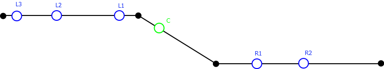
6) Select the center point from those points (SpatialFilter), and merge its measure value to every intersection point (FeatureMerger, unconditional merging).
7) Divide the intersection points into left hand side and right hand side, by testing whether the measure is less than the measure of center (Tester)
8) For left hand side intersection points:
Sort the points by the measure descending (Sorter).
Add 1-based number (Counter), and create label text (StringConcatenator).
9) For right hand side intersection points:
Sort the points by the measure ascending (Sorter).
Add 1-based number (Counter), and create label text (StringConcatenator).
Takashi