This week I looked at this question on the community.
"I have a 100 ft line that curves and then turns back into a straight line. How can I use FME to only gather the straight line after the curve only. I basically want to cut out the curve and only grab the line after the curve."
This isn't too difficult, but what's interesting is the contrast with last week's question. Last week (click the link to check it out) I took a linear feature like this, created a list of its vertices, and processed those numbers directly. This week I could do the same, but instead I'm going with a spatial approach.
In short, I'm going to divide the line into two-part segments, calculate each segment's angle (bearing or azimuth), and test how much each segment differs from the previous one.
Preparing the Data
The first step is to prepare our data by chopping it into two-point lines. The alternative is to just extract the coordinates and work on them (as I did last week) but this time it's just that bit easier to stay in the world of spatial.
Having got these features, I now find the azimuth of each line. This I do with the FME Hub transformer, the HorizontalAngleCalculator :
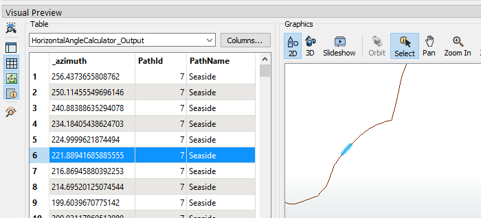
 The first part isn't of interest here. I just pre-process some cycle route data to give me a single line that I can use to demonstrate. Running that through the two transformers so far, I get this:

A series of 2-point lines, each with an azimuth value. The highlighted feature has an azimuth of 221.8 degrees, meaning it is running left-to-right, towards the south-west.
Calculating Offsets
Having these, the basic technique is to calculate the difference in azimuth between a line and the preceding line.
The algorithm I'm using is this:
angle = Math.abs(a1-a2);
if (angle > 180)
    angle = 360 - angle;
Why not just subtract one from the other? Well if one sector has an azimuth of 5 degrees, but the next has the value of 355 degrees, then we know the difference is 10 degrees. But under those circumstances the computer would suggest that 355 - 5 = 350 and 5 - 355 = -350, giving a larger deviation that it really is. So we check the result and adjust as necessary (is it > 180?)
In my workspace I can actually put that into a single function in an arithmetic editor:
(abs(@Value(feature[-1].a)-@Value(a)) <= 180 ? abs(@Value(feature[-4].a)-@Value(a)) : 360 - abs(@Value(feature[-1].a)-@Value(a))What I'm doing there is using a query inside an arithmetic function. The form uses a ? and : characters and is like this:
query ? true value : false valueIf the query is true, set the result to "true value" else set it to "false value". My expression just incorporates the algorithm above to check for a value > 180 and adjust accordingly.
But... I couldn't leave it at that, so I calculated the average differences for the three previous angles. That's because a single angle - taken by itself - isn't indicative of the entire line shape. I think that three vertices gives a better approximation of how far the individual line is curving.
Finally I throw in a test to check if the azimuth difference for the current line, is more than 10 degrees greater than the average azimuth difference for the last three vertices. If so, we can take it that the line is part of a larger curve. So my workspace now looks like this:

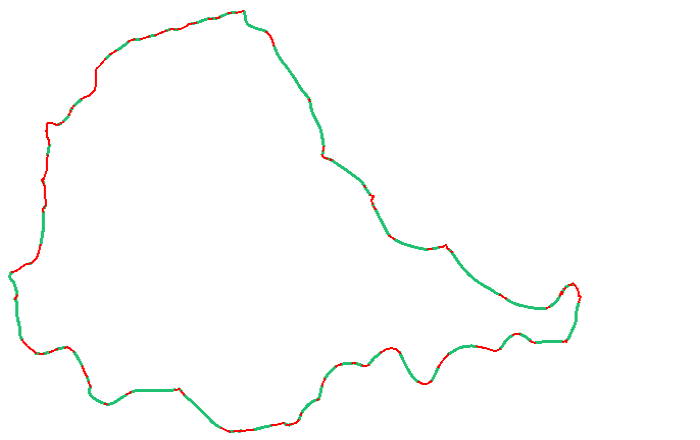
...and the output looks like this:

The thicker, green lines are straight segments; the thinner, red lines are curves. This, incidentally, is the cycle path around Stanley Park in Vancouver. So if the city's parks department wanted to straighten out the path, the red parts are where they should look first.
This should, I believe, help the user to remove the curved part of their line. As always the workspace is attached below.
Thanks
Thanks to Kailin and Dmitri for highlighting the question and suggesting a technique to solve it.


