Question

Alignement LandXML, Put a Attribut of Station/Offset on XYZ Point.

  • 12 March 2024
  • 6 replies
  • 97 views

Badge +1

Hello, I have many points in txt file in PtNum,Y,X,Z,Description etc.
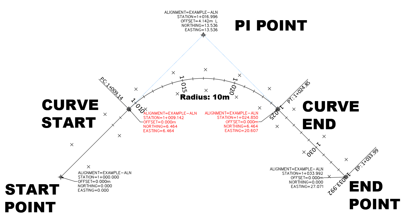
And i have Alignements Geometry in a (Civil3D DWG OR LandXML) I want to put Stationning / Offset value on each point.

Thx alot!!

Running FME 2023.1.1


6 replies

Userlevel 1
Badge +9

Hi, @sylvainl.

Just wanted to clarify a few things.

Firstly, are you comparing the text files and alignment geometries from those file formats to Offset values?

Secondly, are the Offset values stored in the geometries in the Civil3D, DWG, or LandXML file(s)?

Let me know!

Best,

Badge +1

Hello @AliAtSafe (Im sorry for my english)
We have several surveying files in ASCII (CSV) format. They are in the format PtNum,Y,X,Z,Description.
My goal is to do automated processing to generate a report of the differences compared to a surface. For that, I don't have too many problems. However, we use several Roadlines (Alignments either in XML format or in Civil 3D). In Civil 3D with Sincpaq C3D we are easily able to extract the values (Chainage / Offset of the points to store in them). I would like to do the same thing but with FME.

There is a example in Civil 3D with SincPaq (In the circle is the data i want to extract) 
But its calculated in Civil 3D (Alignement geometry: Offset is the perpendicular distance from the point to the line. Station is the distance beetween the start of the line and the intersection) The start can start at any station (for this example the station is 7+000)


Userlevel 1
Badge +9

Hi, @sylvainl.

Thanks for providing an example and detailing your work.

There are a few transformers in FME which can duplicate appending/extracting attributes (i.e., Raw Std, Station, and Offset) that you have accomplished in SincPaq.

The AttributeKeeper, AttributeManager, AttributeRemover, or the BulkAttributeRemover Transformers can append a stream of attributes from different feature types together and continue it onwards to other processes set up.

Let me know if you have already tried this or it works out. I can dig deeper if need be.

Best,

Badge +1

Hello @AliAtSafe ! Thank to trying to help with my case :)

Im just look about the attributes transformer you talked but im not sure how i can use it. Just to be clear:  Raw Station and Offset attributes doesn’t exist. Its a geometry equation. (In construction and road work we use Alignement is a king of coordinate system base on a center line. Its manage curves) We can put a vertical profile too. 
There is a example: i have two point i just import it in a drawing with the alignement . (Normaly i just having Y(north)X(Est),Z(Elevation) in the TXT but in civil 3D we can annotate the point base on the alignement desing.
In FME i can load Alignement but its just like a Polyline with curve (without stationning without notting) Second Image :
Civil 3D:


Userlevel 1
Badge +9

Hi, @sylvainl.

Sorry for the delayed response, was digging deeper into the matter and getting some insight.

I just want to clarify if you are reading in Civil3D as well? If so, as of now, we don't currently support reading Civil 3D alignment station labels, but there is an idea for it here; you can support the idea by upvoting it. If its not exactly what you have in mind you can create an idea by clicking the Start Post button beside your Profile.

For the calculations done in Sincpaq C3D, could you tell me how its done there? I can suggest some processes that can mimic it in FME Form.

My last question is it easier to do the calculations in SincPaq C3D? Would it make more sense to automate creating it in Sincpaq C3D and what goal are you trying to accomplish with FME?

Thanks!

Badge +1

Hello @AliAtSafe :) Sorry for the delay:


I don’t want to pass by Autocad or SincPaq (i have hundreds of files). I want if it possible to calculate all in FME
I make this little example. I posted  ExampleALN.XML
Its a simple Alignement based on only 3 geometry points:
The small X along the alignement is a survey (point in these format : PointNum,Y,X,Z,Decription)
ExampleSurvey.txt
There is the Alignment And survey point in Civil 3D.


Start point at :Y:0 X:0 Starting Station 1+000 or 1000
PI Point at : Y:13.536 X:13.536
End point at Y:0 X:27.071
Curve 10m

Curve start and Curve end are calculated in the software. (FME read a LandXML Alignment geometry correctly its not the point). I think its just don’t import another any useful feature Alignment are built for. Like stationing, Vertical profile.. etc


Its a road Coordinate system itself (All point on the left side of this line are negative
when we talk to engineer, Field surveyor, its more easy to say: Go to 1+005 Offset -5.5m 
instead Y: 5050456.566 X:301874.523 (MTM Z8)


Buy in survey departement We work in a real coordinate system. Road line its just a tool, But nobody cannot visualize complex coordinate.. and we put : Station,Offset on everything to be clear 
We make a lot of survey (thousand) in real coordinate system with Y,X,Z
I want to put the road desing coordinate equivalent. To be more comprehensible for our Quality service. Leica instrument, Trimble instrument, Bentley Inroad, Autodesk Civil3d etc can manage this.

My example is a really easy one but road geometry handle more geometry and more data.
 

Do you know if a way to use correctly in FME ? Thanks alot!


Reply