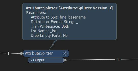
Dear fme users, I'm here to ask your most valuable help. I have hundreds of .dwg files in a directory and I need to process all of them adding 6 attributes to each drawing, the values of these attributes must be taken from the file name. I managed to build a workflow that assigns the attribute values to 6 columns but I can't figure out how to convert this values as recognized attributes by the output file produced with a standard writer.
Small example:
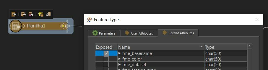
Input file:
- name: ATTRIBUTE1_ATTRIBUTE2.dwg
- no attributes
Output file:
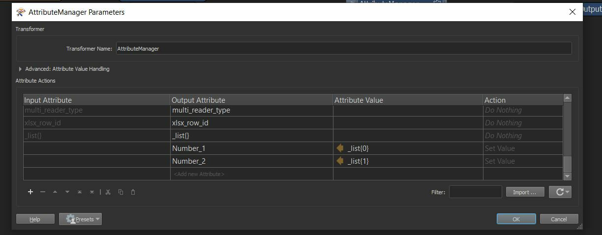
- same name
- two attributes: number one - ATTRIBUTE1 number two - ATTRIBUTE2
Thanks a lot for your help.