I have a line network and need to calculate the angle for each line vertex. I have tried using PolylineAnalyzer but unfortunately it doesn't calculate the angle for all vertices when I used it in the main workspace. Too many vertices miss the angle value.

As for now, I use PolylineAnalyzer in a second workspace which I execute for each line in the line network and write the results to a csv. This does, however, take a looong time. It is the attribute AngleBetweenLines I am after.

Hi

Look at this previous posting by user @gio.

David


Hi

Look at this previous posting by user @gio.

David

Hi David,

The link to the previous posting is pointing to my question.

Could you maybe post the link again?

Thanks

Rickard


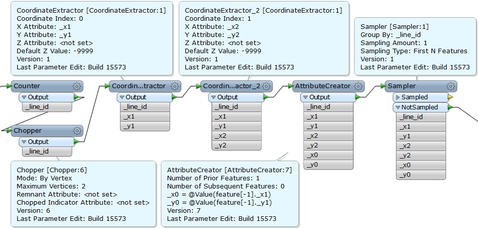
Assume that the angle of each vertex can be calculated based on consecutive 3 coordinates (prior, mid, subsequent) on the line. This data flow extracts the 3 coordinates for each vertex.

  1. Counter: add sequential number to the original line as temporary ID. e.g. "_line_id".
  2. Chopper (Mode: By Vertex, Maximum Vertices: 2): decompose the line into individual line segments.
  3. Two CoordinateExtractors: extract coordinates of start (mid) and end (subsequent) node of the segment. e.g. mid: (_x1, _y1), subsequent: (_x2, _y2).
  4. AttributeCreator: add prior coordinates e.g. (_x0, _y0) to the feature, using the "Enable Adjacent Feature Attributes" option in the AttributeCreator.
  5. Sampler (Group By: _line_id, Sampling Amount: 1, Sampling Type: First N Features): discard the first segment for each original line, because the first segment of a line doesn't have prior vertex.

Then, calculate the angle. Although required math expression may be different according to the definition of "angle", I think it can be calculated based on the consecutive 3 coordinates in any case.


Hi David,

The link to the previous posting is pointing to my question.

Could you maybe post the link again?

Thanks

Rickard

Hi, sorry about that, here's the link I intended to post:

https://knowledge.safe.com/questions/21058/local-bearing-along-a-line.html

David


Thank you for your response Takashi. Your solution works great to extract the vertices needed. I'm still working on the required math expression.


I was actually working on something similar in C# yesterday, and perhaps the following code will help you with your calculations. @takashi is correct in stating that the 3 subsequent coordinates are enough to determine the angle at the second coordinate, you can use his approach for that. Assume we have 6 ordinates x1, y1, x2, y2, x3, y3:

// Determine line segments as vectors.
var vx1 = x2 - x1;
var vy1 = y2 - y1;

var vx2 = x3 - x2;
var vy2 = y3 - y2;

// Calculate vector lengths.
var lengthSegment1 = Math.Sqrt((vx1 * vx1) + (vy1 * vy1));
var lengthSegment2 = Math.Sqrt((vx2 * vx2) + (vy2 * vy2));

// Dot product between two vectors.
var angle = Math.Acos(((vx1 * vx2) + (vy1 * vy2)) / (lengthSegment1 * lengthSegment2));

// NaN occurs at two line segments that are colinear.
if (double.IsNaN(angle))
{
  return 0;
}

// Cross product to determine the side of the line point 3 is, compared to the line p1, p2.
var left = (vx1 * (y3 - y1)) - (vy1 * (x3 - x1)) > 0;

return left ? -angle : angle;

Hope this helps in solving your problem. Note that the answer is in radians, not degrees. Also, don't forget that if you want the angles of all corners you will need to add the second coordinate after the final coordinate, otherwise you won't calculate your start and end point. 


Random thought to avoid angle calculations.


  1. Assign an id to each line (UID)
  2. Chop the features to a maximum of 2 vertices.


  3. TopologyBuilder w/ group by on UID
  4. On the Node output port the _node_angle{}.fme_arc_angle list should have two entries for every feature except the start and end vertices. Subtract the two values to get the angle at that vertex.
Great solution @jdh!


Hi everyone.

I'm trying to make a workflow that extracts lengths, and angles from a polyline(DWG) to a XLS sheet. Every vertex represents a pole where i have a block with info. I need to relate that block with respective vertex and represent it like "Pole01-Pole02 (Angle, Lenght);Pole02-Pole03(Angle, Lenght).

Can anyone give me some lights about this?

Thanks

I think my previous solution with the topology builder should work, just add a LengthCalculator after the chopper and propagate attributes from input on the TopologyBuilder.


Assume that the angle of each vertex can be calculated based on consecutive 3 coordinates (prior, mid, subsequent) on the line. This data flow extracts the 3 coordinates for each vertex.

  1. Counter: add sequential number to the original line as temporary ID. e.g. "_line_id".
  2. Chopper (Mode: By Vertex, Maximum Vertices: 2): decompose the line into individual line segments.
  3. Two CoordinateExtractors: extract coordinates of start (mid) and end (subsequent) node of the segment. e.g. mid: (_x1, _y1), subsequent: (_x2, _y2).
  4. AttributeCreator: add prior coordinates e.g. (_x0, _y0) to the feature, using the "Enable Adjacent Feature Attributes" option in the AttributeCreator.
  5. Sampler (Group By: _line_id, Sampling Amount: 1, Sampling Type: First N Features): discard the first segment for each original line, because the first segment of a line doesn't have prior vertex.

Then, calculate the angle. Although required math expression may be different according to the definition of "angle", I think it can be calculated based on the consecutive 3 coordinates in any case.

I have projected the lines to the dynamic equal distance projection before taking advantage of your solution. I am confused by the coordinates that are output. Some negative, some positive within the same lineid. Is this correct? Is there a flaw in my model?


I have projected the lines to the dynamic equal distance projection before taking advantage of your solution. I am confused by the coordinates that are output. Some negative, some positive within the same lineid. Is this correct? Is there a flaw in my model?

Equidistant projections are not conformal, you do not want to use one for calculating angles.


Reply