Solved

SpatialFilter gives unexpected results


fienna
Contributor
Forum|alt.badge.img+4

I'm using FME Workbench version 2023.2.3. 

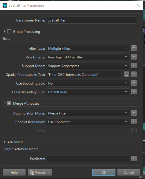
I have 2 datasets, 1 dataset contains around 2,5 million polygons, the other dataset is 1 polygon (a province in this case). I want to know which polygons overlap with the province (even if the overlap is small). I use a SpatialFilter for this, with the 2,5 million polygons as candidate and the 1 polygon of the province as filter. Below are the settings:


Now I noticed some issues, where some polygons who do have an overlap, still end up in the ‘failed’ port. Like the example below:

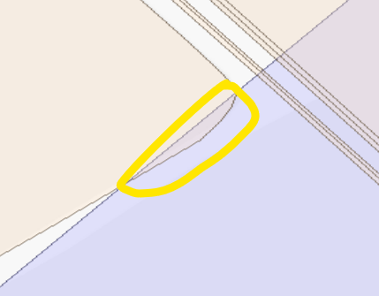
I asked some colleagues and they don't know what's going on here. Everything looks alright and we have no idea why this doesn't go in the ‘passed’ port. It almost seems like a bug. 

I use this SpatialFilter a lot, so I'm curious what's going on here. I hope someone can help me to figure this out. 

Best answer by s.jager

Coincidentally I had this exact problem this morning 😄

Geometries failing OGC validation, for no apparent reason. Turned out to be the Bufferer indeed, whch I use to fix self-intersecting polygons (which, in our data, is usually just two vertices touching - nothing more serious).


There’s a few things you can do (like using the ArcStroker), but what fixed it for me is setting the End Cap Style AND the Corner Style different from the default:

Set them to Square and Miter (or None - Bevel would probably also work) respectively. Theoreticaly that should avoid creating arcs, if you want to be really sure you can add the ArcStroker as well.

View original
Did this help you find an answer to your question?

10 replies

nielsgerrits
VIP
Forum|alt.badge.img+53

Not sure what is happening, but I would isolate both polygons (filter and issue candidate) and send them through a GeometryValidator (attempt repair = Yes) and then try again with the SpatialFilter, to test if this has something to do with geometry being not valid.


s.jager
Influencer
Forum|alt.badge.img+16
  • Influencer
  • October 11, 2024

Apart from what Niels says, I’d check two other things:

  1. Try with Filter Type set to Single Filter
  2. Are the two feature sets the same coordinate system?

bwn
Evangelist
Forum|alt.badge.img+26
  • Evangelist
  • October 12, 2024

Similarly a likely explanation is that the feature X, Ys are in different coordinate systems.

It is better to view them in FME Data Inspector to show screenshots if the workspace features actually intersect or not.  As a quick-and-dirty way I will sometimes also use NeighborFinder to tell me what it thinks is the closest distance for 2 or more features I know should intersect.

If NeighborFinder says more than 0 for closest distance then I know I’ve probably made an error in forgetting to reproject one set of features into the common workspace coordinate system.


fienna
Contributor
Forum|alt.badge.img+4
  • Author
  • Contributor
  • October 14, 2024

Thanks for the replies. 

The coordinatesystems are the same and the geometry is alright. I tried setting Filter type to Single Filter, that didn't help. When I use a Clipper, the part that overlaps is in the inside port (as you would expect). And the NeighborFinder gives a distance of 0. 

I really don't know what's going on. I also just sent a Support Ticket about this too, with the workbench attached to it. 


nielsgerrits
VIP
Forum|alt.badge.img+53

Can you share these 2 geometries as FFS so we can try and reproduce?


s.jager
Influencer
Forum|alt.badge.img+16
  • Influencer
  • October 14, 2024

It may be that either both or one of the two segments of polygon that you show in your screenshot is actually an arc, which could cause something like this. It may be that changing the Curve Boundary Rule setting changes something, but I’m not sure to be honest.

You could also set an attribute for the Predicate, that would at least tell us what SpatialFilter thinks it is - which might give us a clue as well.

Other than that I’m out of ideas, so Niels’ suggestion of sharing the geometries might help us get to the bottom of this.


fienna
Contributor
Forum|alt.badge.img+4
  • Author
  • Contributor
  • October 15, 2024

Thanks @s.jager for your arc suggestion. I took a closer look with a colleague, and we figured out that the Bufferer I'm using to create a buffer around a province, is creating arcs (while the styles are set to Round). Which is weird. Also after the Bufferer the GeometryValidor gives more invalid parts, then before (Failed OGC Simple/Compliant), and the invalidparts output shows arcs. I also installed FME 2024, but that gives the same results. 

I added the workspace in the attached zip (the name is still SpatialFilterBug, but that seems incorrect now I guess)


s.jager
Influencer
Forum|alt.badge.img+16
  • Influencer
  • Best Answer
  • October 15, 2024

Coincidentally I had this exact problem this morning 😄

Geometries failing OGC validation, for no apparent reason. Turned out to be the Bufferer indeed, whch I use to fix self-intersecting polygons (which, in our data, is usually just two vertices touching - nothing more serious).


There’s a few things you can do (like using the ArcStroker), but what fixed it for me is setting the End Cap Style AND the Corner Style different from the default:

Set them to Square and Miter (or None - Bevel would probably also work) respectively. Theoreticaly that should avoid creating arcs, if you want to be really sure you can add the ArcStroker as well.


fienna
Contributor
Forum|alt.badge.img+4
  • Author
  • Contributor
  • October 15, 2024

Thank you @s.jager, changing these settings fixed my problem! An ArcStroker didn't work (strange enough). 

Tho the problem is fixed, this still looks like a bug right? This shouldn't be happening, even if the style settings are on 'round'? 


s.jager
Influencer
Forum|alt.badge.img+16
  • Influencer
  • October 15, 2024

Glad it worked! It did for me as well, so figured it should solve your problem too.


From the documentation it doesn’t look like the Bufferer would create arcs, if you look at the sample images provided:

 But:

Interpolation Angle: Used for the Round End Cap Style and the Round Corner Style. It controls the smoothness of the interpolated lines in the output buffer boundaries, specifying what angles should be used to approximate the circular corner.


In the description for the Interpolation Angle, it does specifically mention “circular corner”. Also the choice of “Round” kinda gives it away. So I do not think it is a bug, I think it works as designed. The documentation could have been clearer in what kind of geometry these settings return, but I don’t think it’s a bug, more an omission in the documentation.


Reply


Cookie policy

We use cookies to enhance and personalize your experience. If you accept you agree to our full cookie policy. Learn more about our cookies.

 
Cookie settings