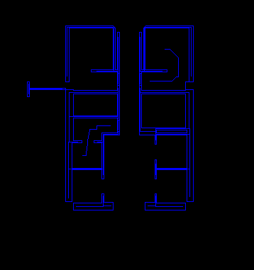
I am struggling with creating centerlines in wall geometry from CAD, where some squirrely ones show up:
 I was hoping that I could filter by # of vertices, or separating by angle, but this is not reliable. Any ideas?
Thanks,
I am struggling with creating centerlines in wall geometry from CAD, where some squirrely ones show up:
 I was hoping that I could filter by # of vertices, or separating by angle, but this is not reliable. Any ideas?
Thanks,
Best answer by redgeographics
I'm guessing it's the ones in the middle of the rooms, which are being formed because the room itself is in fact a closed polygon.
If you have no way of filtering those out through original data attributes you can try using a CircularityCalculator to calculate the circularity of the polygons. The walls being long, thin, polygons will have a very low circularity, the rooms will have a high one. Pass them through a TestFilter and remove the ones that are too high. You'll need to inspect your data first to come up with a good threshold value.