I have a workbench that uses the SurfaceModeller transformer to produce a DEM (DEMRaster output port) from input polylineZ and break lines inputs.


The output DEMRaster will be used as an input in various raster math operations with an existing terrain DEM. It is thus crucial that the DEMRaster output match the cellsize and be perfectly aligned to the existing terrain DEM. In Esri parlance this can be achieved using the "Snap Raster (Environment setting)".


How can I achieve this with FME? I am using FME Desktop Professional 2017.1.1.1.


I have tried using the RasterGeoreferencer as recommended in the Snapping raster output cells to existing raster template cells (same cell size) post. I can either control the extents (using the "Extents" parameter) or the cell spacing (using the "PointAndAngle") but I can't figure out how to control both.


Thanks!

Hi @bme,

I think you will get the best results by creating the surface twice, once for draping and once for the raster generation.

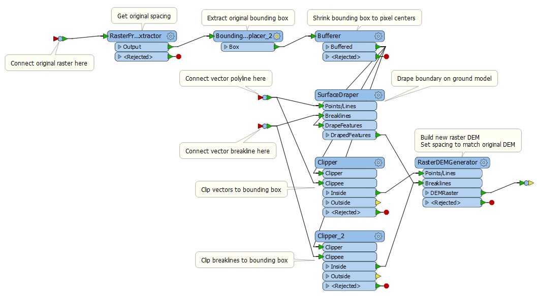
The first step is to extract the boundary of the existing DEMRaster with a BoundingBoxReplacer. Use a Bufferer to buffer it by negative one half of the pixel spacing. This will move the bounding line from the pixel edges to the pixel centers. Use a SurfaceDraper to drape it to 3D on the polylines and breaklines, with Drape Method Model. Use a second copy of the 2D boundary to clip the polylines and breaklines for the next surface model.

Add a RasterDEMGenerator to create the new raster DEM. Use the clipped polylines and breaklines as inputs. Also use the draped boundary as a breakline input - this will force the extent of the surface model to the original raster bounds, and provide the necessary 3D info along that boundary to avoid edge effects. If you use the same spacing in the RasterDEMGenerator, the new raster DEM should overlay the original exactly.

recreaterasterdem.fmw


Reply