Question

Cut 3D-walls with DTM


Badge

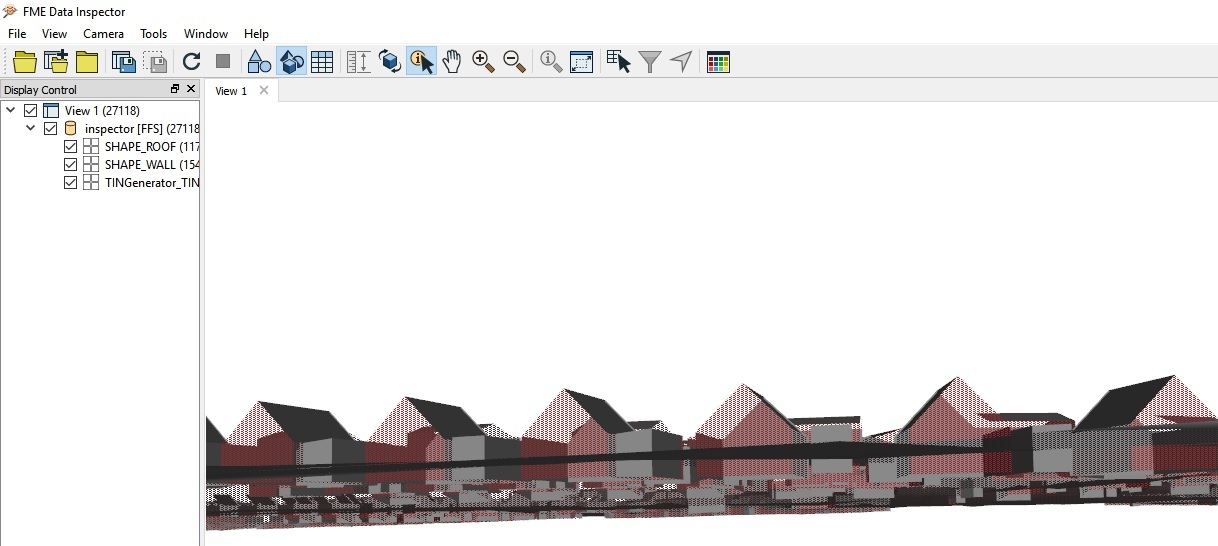
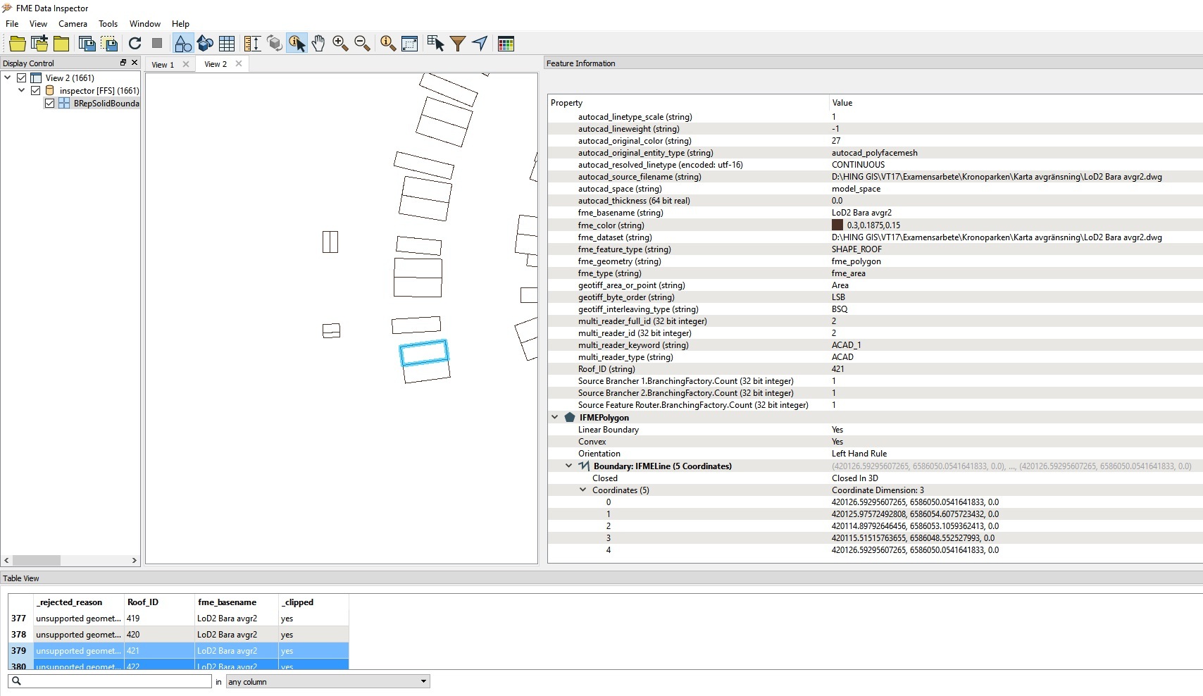
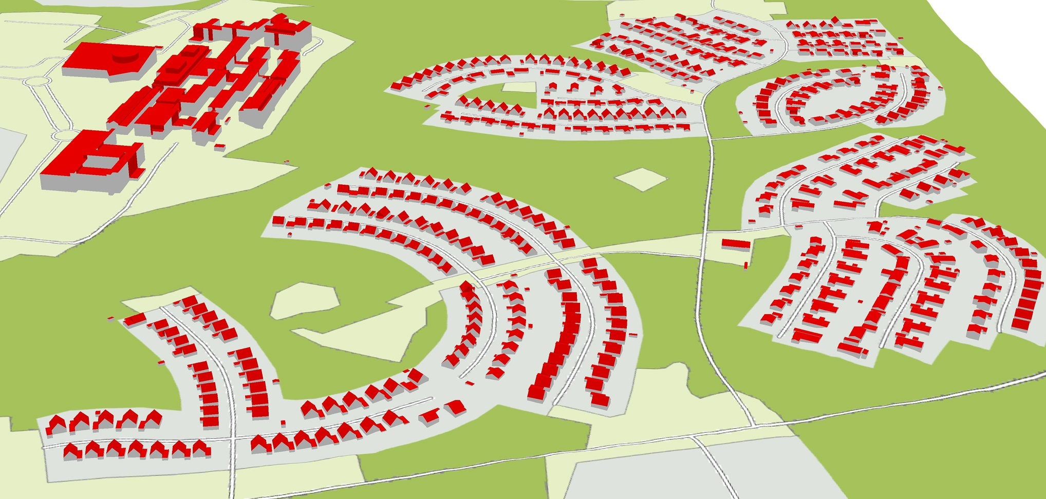
I have Roofs and walls i dwg. But the walls goes 2m to deep in to ground.

Is there any way I can cut the walls with a DTM-raster or TINsurface, or maybe extract new walls from roof to ground.

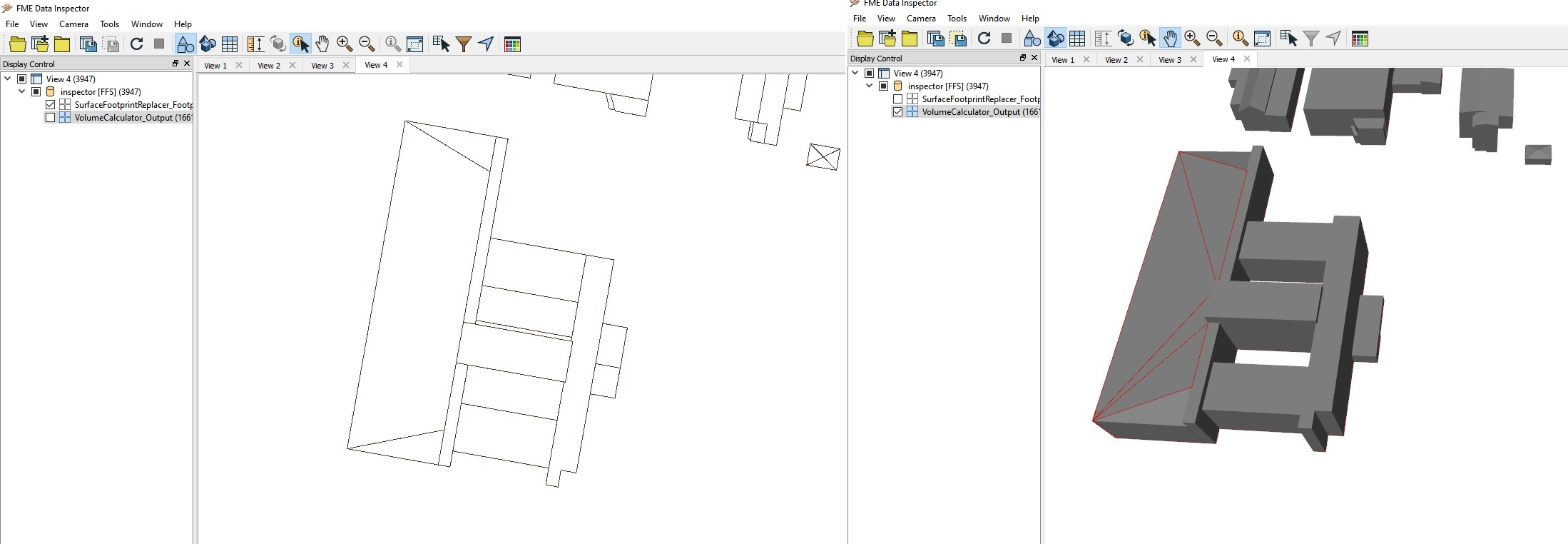
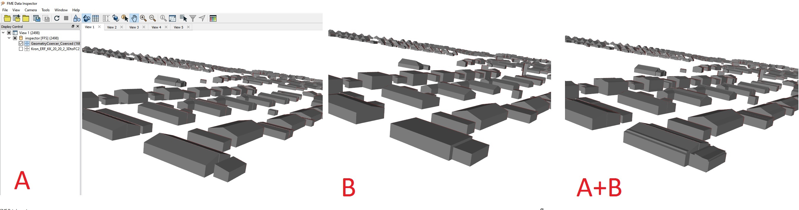
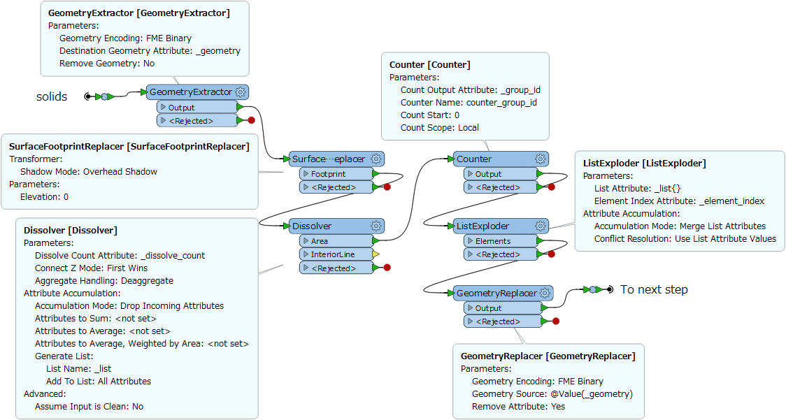
I would also like to have every building as a solid. The floor dose not have to follow the ground. The floor could be level to the buildings lowest point at ground.

Any ideas?


43 replies

Badge +1

Hi,

Not sure can surface be cut with DTM. What I did in simmilar project was to explode Outer eaves (roofs) to vertices and drape them to DTM with SurfaceDraper. Roofs had ID's so i could create facades with them using Point Conector and LineJoiner.

Also, I didn't had to create floors. But using Clipper (roofs on DTM) with group by option should do the trick.

I also remember using FaceReplacer before Aggregator to merge roofs and facades (and also floors if you want them) to surfaces, at the end of whole thing.

Anyway, it was quite a chalenge, so I hope you'll have fun.

Cheers.

Userlevel 2
Badge +17

Hi @antonlarsson10, if each roof is a surface geometry and has a unique ID attribute, the BRepSolidBoundaryCreator.Beta transformer (from the FME Hub) in this context might help you.

  1. SurfaceFootprintReplacer: Create the footprint polygon of the roof surface.
  2. Clipper: Clip the DTM raster by the footprint polygon and merge the roof ID to the clipped raster.
  3. RasterBandMinMaxExtractor: Extract minimum value (ground elevation) of the clipped raster.
  4. FeatureMerger: Merge the ground elevation to the original roof surface, using roof ID as Join On attribute.
  5. BRepSolidBoundaryCreator.Beta (FME Hub): Set the ground elevation to the Planar Surface Elevation parameter.
  6. Aggregator: Aggregate the resulting surfaces from the Top, Side, and Bottom port of the BRepSolidBoundaryCreator.Beta, grouping by the roof ID.
  7. GeometryCoercer (Geometry Type: fme_brep_solid): Transform the aggregate surface into a solid.

Hope this works as expected.

Badge
Thanks for your answers! @takashi and @zzupljanin ,unfortunately I Have no ID. One roof can contain several different parts also.Maybe I could just reduce the z-values of the walls (If there is a way) with - 2 meters. I tried offsetter and it looked good near the ground.


Userlevel 2
Badge +17
Thanks for your answers! @takashi and @zzupljanin ,unfortunately I Have no ID. One roof can contain several different parts also.Maybe I could just reduce the z-values of the walls (If there is a way) with - 2 meters. I tried offsetter and it looked good near the ground.


You can add sequential number to the roofs as their temporary ID with the Counter transformer, and the BRepSolidBoundaryCreator.Beta works for any type surface geometry including IFMECompositeSurface.


Badge

Hi @antonlarsson10, if each roof is a surface geometry and has a unique ID attribute, the BRepSolidBoundaryCreator.Beta transformer (from the FME Hub) in this context might help you.

  1. SurfaceFootprintReplacer: Create the footprint polygon of the roof surface.
  2. Clipper: Clip the DTM raster by the footprint polygon and merge the roof ID to the clipped raster.
  3. RasterBandMinMaxExtractor: Extract minimum value (ground elevation) of the clipped raster.
  4. FeatureMerger: Merge the ground elevation to the original roof surface, using roof ID as Join On attribute.
  5. BRepSolidBoundaryCreator.Beta (FME Hub): Set the ground elevation to the Planar Surface Elevation parameter.
  6. Aggregator: Aggregate the resulting surfaces from the Top, Side, and Bottom port of the BRepSolidBoundaryCreator.Beta, grouping by the roof ID.
  7. GeometryCoercer (Geometry Type: fme_brep_solid): Transform the aggregate surface into a solid.

Hope this works as expected.

I'm a beginner so thanks for your patience!


I cant get the clipper to work. But except that is the canvas like you described?


Userlevel 2
Badge +17
I'm a beginner so thanks for your patience!


I cant get the clipper to work. But except that is the canvas like you described?


I suspect that there could be vertical (wall-like) surfaces in the SHAPE_ROOF dataset. The SurfaceFootprintReplacer transforms a vertical surface into a line and the Clipper rejects lines input as Clippers.


Anyway, connect an Inspector to the <Rejected> port of the Clipper and run the workspace to check what kind of features were rejected, then consider how the rejected features should be handled.


Additionally, you have to modify these points.


  • In the Clipper, you should NOT set the Group By parameter. Roof_ID will be transferred from the Clipper (footprint) to the Inside clipped raster feature.
  • Remove the Aggregator_2 and the Aggregator_3, and connect all the Top, Side, and Bottom ports of the BRepBoundaryCreator.Beta to the Aggregator.
Badge
I suspect that there could be vertical (wall-like) surfaces in the SHAPE_ROOF dataset. The SurfaceFootprintReplacer transforms a vertical surface into a line and the Clipper rejects lines input as Clippers.


Anyway, connect an Inspector to the <Rejected> port of the Clipper and run the workspace to check what kind of features were rejected, then consider how the rejected features should be handled.


Additionally, you have to modify these points.


  • In the Clipper, you should NOT set the Group By parameter. Roof_ID will be transferred from the Clipper (footprint) to the Inside clipped raster feature.
  • Remove the Aggregator_2 and the Aggregator_3, and connect all the Top, Side, and Bottom ports of the BRepBoundaryCreator.Beta to the Aggregator.
Yes it says invalid clipper geometry


Userlevel 2
Badge +17
Yes it says invalid clipper geometry


If you can ignore (discard) the invalid geometries, I think the workspace works for you after modifying the two points I pointed in the previous post.


Badge
Yes it says invalid clipper geometry


I think I manage to do that but now it stops at FeatureMerger.


Userlevel 2
Badge +17
Yes it says invalid clipper geometry


Why did you change the Join On setting? Try restoring it to the previous setting.


Badge
I'm a beginner so thanks for your patience!


I cant get the clipper to work. But except that is the canvas like you described?


Sorry I misunderstood. Now the BRepSolidBoundaryCreator.Beta rejects all. In inspector it say rejected reason: unsupported geometry type


Userlevel 2
Badge +17
Sorry I misunderstood. Now the BRepSolidBoundaryCreator.Beta rejects all. In inspector it say rejected reason: unsupported geometry type


What is the internal geometry class of the rejected features? Check the geometry class (IFME***) with Logger or Data Inspector (Feature Information).


The BRepSolidBoundaryCreator.Beta supports geometries of IFMESurface class (IFMEFace, IFMEMesh, IFMERectangleFace, IFMETriangleFan, IFMETriangleStrip, and IFMECompositeSurface), but doesn't support IFMEMultiSurface and IFMEAggregate consisting of multiple surfaces.


Badge
What is the internal geometry class of the rejected features? Check the geometry class (IFME***) with Logger or Data Inspector (Feature Information).


The BRepSolidBoundaryCreator.Beta supports geometries of IFMESurface class (IFMEFace, IFMEMesh, IFMERectangleFace, IFMETriangleFan, IFMETriangleStrip, and IFMECompositeSurface), but doesn't support IFMEMultiSurface and IFMEAggregate consisting of multiple surfaces.


It says IFMEPolygon


Under it says Boundary: IFMELine


Userlevel 2
Badge +17
Sorry I misunderstood. Now the BRepSolidBoundaryCreator.Beta rejects all. In inspector it say rejected reason: unsupported geometry type


oops, I missed. Connect the Counter to the FeatureMerger directly, rather than the SurfaceFootprintReplacer.


Badge
It says IFMEPolygon


Under it says Boundary: IFMELine


Now it's working!


Many thanks for all the help!


regards,


Anton
Badge
Now it's working!


Many thanks for all the help!


regards,


Anton
Now the buildings are separated in different segments, is it possible to make every building as one solid part?


In the end i want to compare the buildings with other buildings at same location but from different source. When the building is in parts it's hard to make a spatial filter to work because at some places it will even join attributes from surrounding building. I want to get the same ID on the buildings i want to compare.


B is solid and ready to go. Exported as 3d feature from ArcGIS Pro
Userlevel 2
Badge +17

> make every building as one solid part?

It could be a bit complex. A possible way I can think of is:

Step 1

Step 2

Badge

> make every building as one solid part?

It could be a bit complex. A possible way I can think of is:

Step 1

Step 2

Thanks!


It seems to work except for the clipper. I cant fint the Z and Mesures Parameters.


The rejected clipees says Invalid_Clipper_Geometry_Type


Userlevel 2
Badge +17
Thanks!


It seems to work except for the clipper. I cant fint the Z and Mesures Parameters.


The rejected clipees says Invalid_Clipper_Geometry_Type


No problem. The Z and Measure parameters have been introduced into the Clipper in FME 2017.0, but do not affect this case.


Badge
No problem. The Z and Measure parameters have been introduced into the Clipper in FME 2017.0, but do not affect this case.


Okej. But nothing is passing the clipper from the inside-port. The rejected ones looks solid and the ones from the tester is some roofs not solid.


Should i use the result from this and run in the other canvas that you showed me before?


Thanks!
Userlevel 2
Badge +17
No problem. The Z and Measure parameters have been introduced into the Clipper in FME 2017.0, but do not affect this case.


Firstly you have to create solids from the roof surfaces and the DTM raster with the procedure (1-8) that I suggested first. Then, send the resulting solids to the Step 1 -> Step 2. All should be implemented as a single workspace in the Main canvas.


Badge
Okej. But nothing is passing the clipper from the inside-port. The rejected ones looks solid and the ones from the tester is some roofs not solid.


Should i use the result from this and run in the other canvas that you showed me before?


Thanks!
Yes i did it but it seems like it is something wrong with the dissolver? Lots of lines is still left. Like with the clipper i didn't had all the parameter-options


Se result below.


The outport rejected clipper seems to give a good result.


Userlevel 2
Badge +17
Thanks!


It seems to work except for the clipper. I cant fint the Z and Mesures Parameters.


The rejected clipees says Invalid_Clipper_Geometry_Type


Can you post roof data example including some relatively complex roofs like shown in the last screenshot?


Badge
Can you post roof data example including some relatively complex roofs like shown in the last screenshot?


The area in last screenshot is the only buildings with complex roof. All the other buildings are flat, shed or gable.


The whole area looks like this:


Here is some more data over the complex area. I hope you can see the attributes.


What I want to do is compare this buildings, as I see as "reference" because of low Measurement uncertainty (made by a company) with my buildings i made by myself with LiDAR-data. I have tried to use the spatial filter to transfer attributes based on spatial location. But because (I think) the reference buildings are in segments (see pic below).


The steps 1-8 you showed me first was really helpful because i could run the volume counter and manually count the volume of every segment from one building to get the result (I will use volume to see difference between my buildings and the reference buildings). But to make the reference buildings as solid I think it's easier to automatically count the volumes of every building and compare the based on spatial location.


I just wanted to explain what my goal is with this.


I really appreciate your help.


Userlevel 2
Badge +17
The area in last screenshot is the only buildings with complex roof. All the other buildings are flat, shed or gable.


The whole area looks like this:


Here is some more data over the complex area. I hope you can see the attributes.


What I want to do is compare this buildings, as I see as "reference" because of low Measurement uncertainty (made by a company) with my buildings i made by myself with LiDAR-data. I have tried to use the spatial filter to transfer attributes based on spatial location. But because (I think) the reference buildings are in segments (see pic below).


The steps 1-8 you showed me first was really helpful because i could run the volume counter and manually count the volume of every segment from one building to get the result (I will use volume to see difference between my buildings and the reference buildings). But to make the reference buildings as solid I think it's easier to automatically count the volumes of every building and compare the based on spatial location.


I just wanted to explain what my goal is with this.


I really appreciate your help.


If the goal is just to compute the volume of each building (and if roofs in the dataset never overlap each other), MultiSolid features which will be output via the Aggregator could be useful enough and the final clipping operation in the Step 2 may not be necessary.


Reply