Solved

Reading DWG with "correct" justification.

  • 17 February 2022
  • 8 replies
  • 14 views

Badge

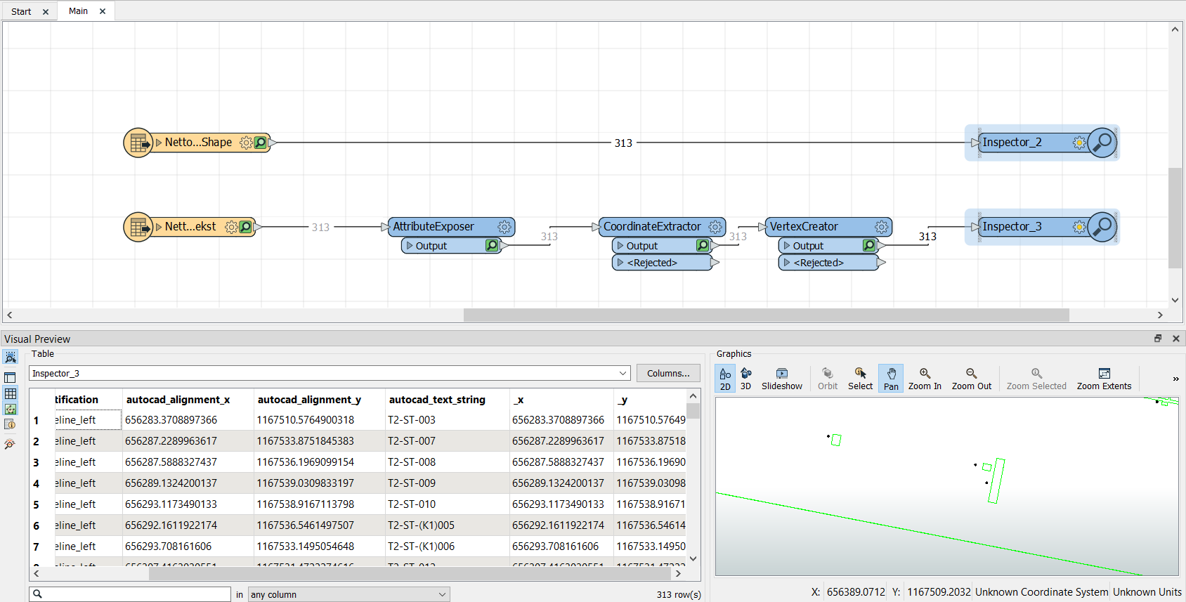
I have a workflow in which i convert .dgn and .dwg files to postgis, in this process I spatially join the text to areas, as I need them for attributes.

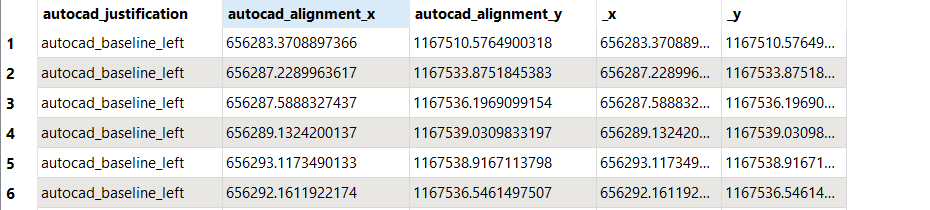
My problem is the text alignment for the dwg files is baseline_left.

Even though my colleague centered these. imageimage
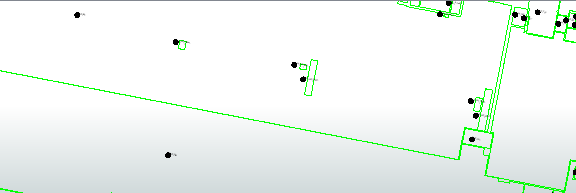
Is there any workaround, or possibility to get the placement to center?

I've tried using an offsetter, but the areas are very different in size, so the offset is not uniform distributed between the points.


The .dgn files does not have this problem.


EDIT:

The problem is that:

the placement of the points are not what my colleague sees in her program, there they are centered.

But they are not centered in the areas when I open the file in FME.


Thanks in advance

Jonathan

icon

Best answer by jonathanklarup 18 February 2022, 07:16

View original

8 replies

Userlevel 4
Badge +26

Hmm, interesting so FME is interpreting the justification wrong?

You could try and turn this setting off in the reader - it might prevent FME from trying to calculate the position of the text. The point should still be there with the text string as an attribute, just not visible in the data inspector

image.pngSome more Information:

https://docs.safe.com/fme/html/FME_Desktop_Documentation/FME_ReadersWriters/acad/Text_Entities.htm

And some more :

https://community.safe.com/s/article/text-justification#:~:text=Justification%20refers%20to%20the%20position,right%20of%20the%20origin%20point.

Badge +20

Your answer is in the screenshot you posted.

AutoCAD stores the insertion points of texts/mtexts as autocad_alignment_x/y/z

Expose autocad_text_string and rename the attribute and use VertexCreator in mode Replace with Point and autocad_alignment_x, autocad_alignment_y as X and Y Values.

Then do point on area or any preferred spatial join.

Badge

Hmm, interesting so FME is interpreting the justification wrong?

You could try and turn this setting off in the reader - it might prevent FME from trying to calculate the position of the text. The point should still be there with the text string as an attribute, just not visible in the data inspector

image.pngSome more Information:

https://docs.safe.com/fme/html/FME_Desktop_Documentation/FME_ReadersWriters/acad/Text_Entities.htm

And some more :

https://community.safe.com/s/article/text-justification#:~:text=Justification%20refers%20to%20the%20position,right%20of%20the%20origin%20point.

Yes it looks like.

Unfortunately the "read visible attributes as text entities" parameter does not solve the problem, as the points which I think are defined by the autocad_alignment_x and y are wrongly placed.


I must admit that I'm a geographer and I'm specialized in GIS, and fairly in working with cad drawings.

And therefore I'm not sure whether its the FME part or my colleagues work which is the problem. Though my colleague insists that they points are center placed.

I read on a few different forums about a bug where dwg files be default switches back to the default justification baseline_left, could this maybe be the problem?

And if can I force it from another program to stay middle_center ?

Badge

Your answer is in the screenshot you posted.

AutoCAD stores the insertion points of texts/mtexts as autocad_alignment_x/y/z

Expose autocad_text_string and rename the attribute and use VertexCreator in mode Replace with Point and autocad_alignment_x, autocad_alignment_y as X and Y Values.

Then do point on area or any preferred spatial join.

Unfortunately I have tried this.

The autocad_alignment_x and y are the same as the points shown in the first picture, as you can see I've extracted the coordinates from the points and they are completely the same.

So maybe the problem comes from my colleague, and isn't something I can fix in FME?


image

Userlevel 4
Badge +26

Yes it looks like.

Unfortunately the "read visible attributes as text entities" parameter does not solve the problem, as the points which I think are defined by the autocad_alignment_x and y are wrongly placed.


I must admit that I'm a geographer and I'm specialized in GIS, and fairly in working with cad drawings.

And therefore I'm not sure whether its the FME part or my colleagues work which is the problem. Though my colleague insists that they points are center placed.

I read on a few different forums about a bug where dwg files be default switches back to the default justification baseline_left, could this maybe be the problem?

And if can I force it from another program to stay middle_center ?

Another thing to try would be to use the other Autocad reader to see if there is any difference. You can compare both the ACAD and REALDWG reader to see if there is a difference. Pretty hard to assign blame here really - One thing would be to open it up in autocad again, and mess around with one/some of the labels to see if you can get any different behaviour.

If all else fails you can send it to safe support and have them look at it.


Badge

Yes it looks like.

Unfortunately the "read visible attributes as text entities" parameter does not solve the problem, as the points which I think are defined by the autocad_alignment_x and y are wrongly placed.


I must admit that I'm a geographer and I'm specialized in GIS, and fairly in working with cad drawings.

And therefore I'm not sure whether its the FME part or my colleagues work which is the problem. Though my colleague insists that they points are center placed.

I read on a few different forums about a bug where dwg files be default switches back to the default justification baseline_left, could this maybe be the problem?

And if can I force it from another program to stay middle_center ?

Yea We'll try to open it in autocad again and mess around. Thank you :)

Badge +20

Unfortunately I have tried this.

The autocad_alignment_x and y are the same as the points shown in the first picture, as you can see I've extracted the coordinates from the points and they are completely the same.

So maybe the problem comes from my colleague, and isn't something I can fix in FME?


image

Then your colleagues placed the "centre aligned texts" in CAD so they look good, not so they have the insertion points in the corresponding areas.

This is a common problem when integrating AutoCAD data in GIS.

FME doesn't care of the alignment of texts 😀

Badge

@caracadrian​ @virtualcitymatt​ 

Just figured this out, and I'm not sure it will always work.

First of the problem is a conversion error when my colleague converts from dgn to dwg, so others may experience the same.

If I make a bounding box around the text, convert it to centerlines and take the 0 index coordinate I get this :

imageThough I'm still unsure whether it's the best way, I might think we should do the conversion from dgn to dwg in FME, here the autocad_aligment corresponds to the v8 points.

But hey it's a solution too 🙂


Thanks for the help, have a nice day.


EDIT:

It does not fix all the problems, either I have to rotate the text or I might have to do an overlay with lines and sort the areas out one by one with overlap values.

Reply