Solved

DXF/DWG Writer: Write 3D - polygons added


Badge

Hi everyone.

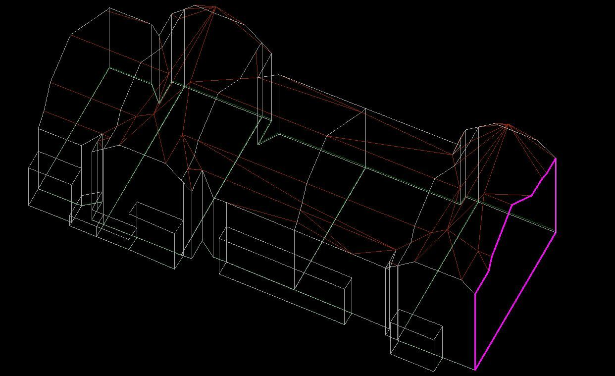
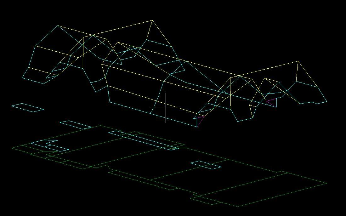
If I make an export to dxf from my 3D database (CityGRID) with their tools and inspect the result in Microstation my buildings look as expected:

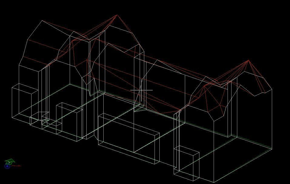
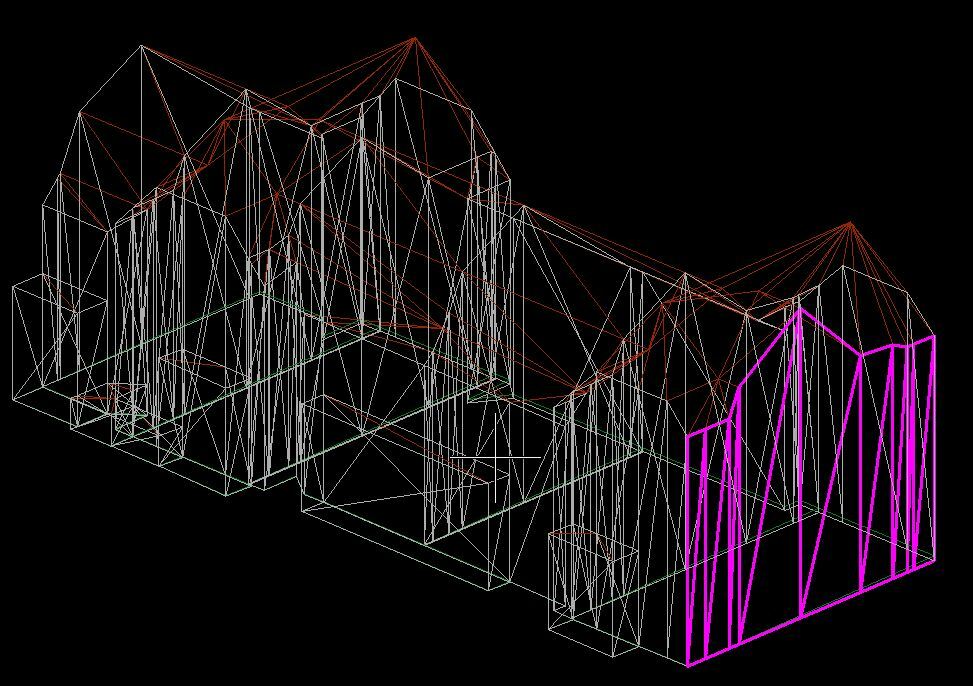
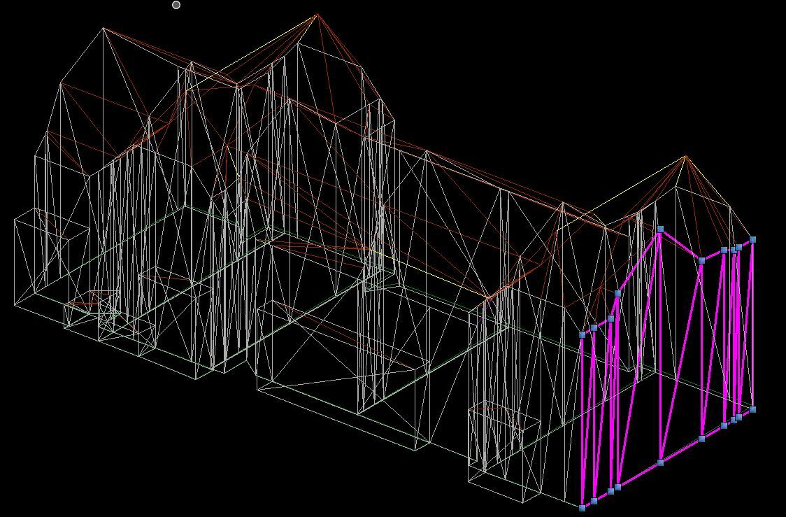
As soon as I touch the buildings with FME for further processing, even if it is just read and write to dxf again, tho whole thing is "polygonized":

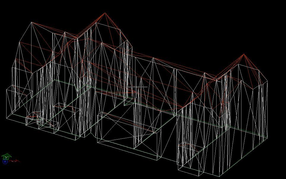
Even though the building is still "correct" the result looks to nervous to me (and to our customers as well).

Is there a way to tell FME not to polygonize areas with the same normal? Or at least a switch that tells the CAD-Software not to show these polygons?

Thank you very much for any hints.

Simon

icon

Best answer by fmelizard 7 July 2017, 22:39

View original

25 replies

Badge +10

Hi @simon11,

What you see in the second image looks like a triangulation of your polygons. I do not know what you want to do with the data, but you could consider writing the features as lines, if you only want to see the edges.

For Microstation I do not know if there is a possibility to turn of the polygons as you state. In AutoCAD I know it is possible to turn-on and -off the fill of a polygon, but I am not sure whether you can only display the wire frame without the triangulation.

I hope this helps.

Kind regards, Lars


Badge +8

could you please explain what you mean by touching and also nervous. Could you describe what kind of processing you would like to do? Just trying to narrow down to the problem.

Badge

Hi @lars_de_vries and @gisinnovationsb

Thank you for your quick answers! I want the buildings to stay the way they are after I exported them out of my 3D-database. In future processes I only want to add additional data and not do anything with the buildings at all.

What I have done so far:

  • 1. Export from DB to DXF with DB-Tools: first picture
  • 2. Test translation DXF to DXF (nothing more): second picture

Future 2: Add additional Data to the DXF from 1 but leave the buildings as they are.

Since the test translation without adding any data or manipulating the buildings gave me the triangulated 2nd picture (for me it looks nervous with all these lines) I thought there must be a way to prevent the triangulation.

So the goal is to load DXF from 1 into FME, do wathever without manipulating the buildings themselves and write to DXF again without these triangulationlines.

Badge +7

Hi @lars_de_vries and @gisinnovationsb

Thank you for your quick answers! I want the buildings to stay the way they are after I exported them out of my 3D-database. In future processes I only want to add additional data and not do anything with the buildings at all.

What I have done so far:

  • 1. Export from DB to DXF with DB-Tools: first picture
  • 2. Test translation DXF to DXF (nothing more): second picture

Future 2: Add additional Data to the DXF from 1 but leave the buildings as they are.

Since the test translation without adding any data or manipulating the buildings gave me the triangulated 2nd picture (for me it looks nervous with all these lines) I thought there must be a way to prevent the triangulation.

So the goal is to load DXF from 1 into FME, do wathever without manipulating the buildings themselves and write to DXF again without these triangulationlines.

Could you post a screenshot of the DXF Reader parameters?


And to rule out whether the Reader or the Writer is the problem, could you connect a Data Inspector to the Reader, select a geometry and make a screenshot? I'd like to know the geometry type.


But even better would be to upload the DXF here so we can inspect it ourselves, if your customer would allow that...


Badge

Attached you'll find:

in.dxf: my inputfile, the way the building should stay

out.dxf: output of FME-translation: "destroyed" building

dxf2dxf.fmw: testworkbench.

Thanks

simons-problem.zip

Badge +7

It seems to me that both the in.dxf and out.dxf are almost exactly the same in FME.


When I inspect the input file and the output file in the Data Inspector, I don't see any differences, except for the fact that the autocad_entity_handle has changed and that autocad_original_color has received a value. But I don't think that should matter.

Please note that the file contains both 3D polylines (autocad_entity = autocad_line) and surfaces (autocad_entity = autocad_surface). Surfaces are always triangulated, but they should not be exploded into individual triangles. If you click on the white triangles from the out.dxf file in MicroStation, does it actually highlight a single triangle then or the whole wall part (a group of triangles)?


I did notice that the autocad_original_entity_type = autocad_polyfacemesh (already on the Reader/in.dxf), so it seems that FME performs some internal conversion? Not sure if anything has to do with this, but when I read the documentation, it says:For writing, all 3D surface geometry types are supported. Any types of 3D geometry which are not directly supported as entities are decomposed into triangulated mesh representation prior to writing.

Also, there are some tips in the documentation that tell you how you should configure the DXF Reader when you perform an ACAD->ACAD conversion. I've created a Reader with those settings, added a Writer (dynamic mode) and created the file out-dynamicdxf.zip. It probably doesn't do much, but could you please check in MicroStation if this makes a difference?

If you don't see a difference, you could try to use a Triangulator on the surface geometries (that will convert the composite surfaces to meshes) and write a new DXF like I did in the file workspace.zip.

If THAT doesn't work, then I don't know what's causing this...

Badge +11

It seems to me that both the in.dxf and out.dxf are almost exactly the same in FME.


When I inspect the input file and the output file in the Data Inspector, I don't see any differences, except for the fact that the autocad_entity_handle has changed and that autocad_original_color has received a value. But I don't think that should matter.

Please note that the file contains both 3D polylines (autocad_entity = autocad_line) and surfaces (autocad_entity = autocad_surface). Surfaces are always triangulated, but they should not be exploded into individual triangles. If you click on the white triangles from the out.dxf file in MicroStation, does it actually highlight a single triangle then or the whole wall part (a group of triangles)?


I did notice that the autocad_original_entity_type = autocad_polyfacemesh (already on the Reader/in.dxf), so it seems that FME performs some internal conversion? Not sure if anything has to do with this, but when I read the documentation, it says:For writing, all 3D surface geometry types are supported. Any types of 3D geometry which are not directly supported as entities are decomposed into triangulated mesh representation prior to writing.

Also, there are some tips in the documentation that tell you how you should configure the DXF Reader when you perform an ACAD->ACAD conversion. I've created a Reader with those settings, added a Writer (dynamic mode) and created the file out-dynamicdxf.zip. It probably doesn't do much, but could you please check in MicroStation if this makes a difference?

If you don't see a difference, you could try to use a Triangulator on the surface geometries (that will convert the composite surfaces to meshes) and write a new DXF like I did in the file workspace.zip.

If THAT doesn't work, then I don't know what's causing this...

This issue is a question of showing internal edges of a mesh and not a question of triangulation! Meshes have to be triangulated by default, but some software can mask internal edges. For AutoCAD meshes (polyface mesh) you can specify for every edge if it should be visible or not. So this leads us to the question if there is a swich for FME to turn on this display behaviour or not.


Badge +7
This issue is a question of showing internal edges of a mesh and not a question of triangulation! Meshes have to be triangulated by default, but some software can mask internal edges. For AutoCAD meshes (polyface mesh) you can specify for every edge if it should be visible or not. So this leads us to the question if there is a swich for FME to turn on this display behaviour or not.


I know that all meshes are triangulated. The thing is that FME reads it as a composite surface, which is like an aggregate of (potentially triangular) faces. By forcing it into a mesh, I was hoping that it might not show the behaviour in MicroStation that @simon11 is seeing (please note that the screenshot he posted are not made with FME - the Data Inspector does not show the edges).


However, you do bring up something interesting as FME might drop some kind of display setting in the DXF. I did notice that there are some attributes on the wall surface parts that were triangular already in the original DXF:


So this autocad_edge_n attribute might need to be set to "hidden"? Would be a bit of a pain to generate an attribute for each edge and then it still remains to be seen if the DXF Writer can deal with it.
Badge

Thank you all for your inputs!

@sander_s (what am I doing wrong with the notifying??) unfortunately your out_dynamic.dxf looks the same as my second picture so no visible changes.

Concerning highlighting in Microstation.


If I click on a face in out.dxf the selection looks like this:

And if I click on a wall in in.dxf the selection looks like this:

In the meantime I've got an answer from the software developer of my database program: what they are doing when exporting to dxf is that they identify these “unnecessary” triangle-lines and flag them as “egde invisible” whereas the rest is set to “edge visible”. But where is this attribute stored and how can I prevent FME to reset it?

Badge +8

Thank you all for your inputs!

@sander_s (what am I doing wrong with the notifying??) unfortunately your out_dynamic.dxf looks the same as my second picture so no visible changes.

Concerning highlighting in Microstation.


If I click on a face in out.dxf the selection looks like this:

And if I click on a wall in in.dxf the selection looks like this:

In the meantime I've got an answer from the software developer of my database program: what they are doing when exporting to dxf is that they identify these “unnecessary” triangle-lines and flag them as “egde invisible” whereas the rest is set to “edge visible”. But where is this attribute stored and how can I prevent FME to reset it?

Hi. Can we have a screenshot of that flag? Thanks.


Badge
Hi. Can we have a screenshot of that flag? Thanks.


Unfortunately that is all they told me. Where and when they set this flag I don’t know.


I ask them for detailed informations.


Badge +7

Hi @simon11,

Thanks for the screenshots. It's good to see that FME does not explode the surfaces into individual triangles.

This was already mentioned in my comment above somewhere (following up on @whkarto), but yes, there is indeed a display setting that is stored in an attribute (autocad_edge_<n>), but I only observe it on surface parts that are triangular:

Diving a little deeper into the documentation, this seems to be supported by FME, at least for autocad_face entities. It seems that FME only supports these attributes on individual triangle (sur)faces (although I don't understand why a triangle should have 4 edges instead of 3...), but drops it on surfaces that consist of more than 1 triangle. Either way, the value of the attribute should be set to "invisible" for those edges that you don't want to see.

Now we can try out the following:

See what happens if we set an autocad_edge_<n> attribute for all surfaces ourselves. Just create the attributes (1-4) on all surfaces (not the lines!) and set them to invisible to test if the FME Writer picks it up and if MicroStation hides some of the edges. I'm curious how this will look, especially on the surfaces that consist of more than 1 triangle! Are only a few edges invisible? Are all of them invisible? Or are they all visible (which is probably the case, I fear)?

If you see that the individual triangles (like the one on the roof) are completely invisible and that the composite surfaces only have a few (or all) invisible edges, then we're in luck and we can continue creating a workspace that sets all the edges properly.

I've already created the DXF files for you to test. The file out_invisible_edges.dxf is the same as the original, but upon writing, I have set the autocad_edge attribute on all of them (triangular or not). The file out_invisible_edges_triangles.dxf is similar, but here I have used a Deaggregator to make sure that we only output true triangles. I know, that's not what you want, but it's just to test if the autocad_edge attribute has an effect on output DXF.

out-dxf-edges.zip

Badge

Hi @simon11,

Thanks for the screenshots. It's good to see that FME does not explode the surfaces into individual triangles.

This was already mentioned in my comment above somewhere (following up on @whkarto), but yes, there is indeed a display setting that is stored in an attribute (autocad_edge_<n>), but I only observe it on surface parts that are triangular:

Diving a little deeper into the documentation, this seems to be supported by FME, at least for autocad_face entities. It seems that FME only supports these attributes on individual triangle (sur)faces (although I don't understand why a triangle should have 4 edges instead of 3...), but drops it on surfaces that consist of more than 1 triangle. Either way, the value of the attribute should be set to "invisible" for those edges that you don't want to see.

Now we can try out the following:

See what happens if we set an autocad_edge_<n> attribute for all surfaces ourselves. Just create the attributes (1-4) on all surfaces (not the lines!) and set them to invisible to test if the FME Writer picks it up and if MicroStation hides some of the edges. I'm curious how this will look, especially on the surfaces that consist of more than 1 triangle! Are only a few edges invisible? Are all of them invisible? Or are they all visible (which is probably the case, I fear)?

If you see that the individual triangles (like the one on the roof) are completely invisible and that the composite surfaces only have a few (or all) invisible edges, then we're in luck and we can continue creating a workspace that sets all the edges properly.

I've already created the DXF files for you to test. The file out_invisible_edges.dxf is the same as the original, but upon writing, I have set the autocad_edge attribute on all of them (triangular or not). The file out_invisible_edges_triangles.dxf is similar, but here I have used a Deaggregator to make sure that we only output true triangles. I know, that's not what you want, but it's just to test if the autocad_edge attribute has an effect on output DXF.

out-dxf-edges.zip

Thank you very much for your detailed answers!


So, we now have following results if opened in Microstation:


out_invisible_edges.dxf:


out_invisible_edges_triangles.dxf:


Sorry I am rather new to writing 3D-faces to DXF with FME - what does this mean to us now?


Badge +7
Thank you very much for your detailed answers!


So, we now have following results if opened in Microstation:


out_invisible_edges.dxf:


out_invisible_edges_triangles.dxf:


Sorry I am rather new to writing 3D-faces to DXF with FME - what does this mean to us now?


Ah, great @simon11! Thanks for the screenshots again.


So the good news is that FME seems to support it on individual triangles (as nothing is visible in the second image). The bad news is, that it doesn't have any effect on composite surfaces, so it seems. To rule that out, could you verify something for out_invisible_edges.dxf? Only show 1 composite surface (for instance the pink selected one) and hide/delete the rest in MicroStation. Make sure the surface is deselected. Do you see all edges, i.e. does it look the same as the pink selected one in the screenshot above?


Badge
Ah, great @simon11! Thanks for the screenshots again.


So the good news is that FME seems to support it on individual triangles (as nothing is visible in the second image). The bad news is, that it doesn't have any effect on composite surfaces, so it seems. To rule that out, could you verify something for out_invisible_edges.dxf? Only show 1 composite surface (for instance the pink selected one) and hide/delete the rest in MicroStation. Make sure the surface is deselected. Do you see all edges, i.e. does it look the same as the pink selected one in the screenshot above?


I am not sure if I undarstand correctly - if I select the pink part and delete the rest, the pink part stays the same (visible triangles).


Badge +7
I am not sure if I undarstand correctly - if I select the pink part and delete the rest, the pink part stays the same (visible triangles).


Yes exactly @simon11. Do you still see all edges after you deselect it (when it's no longer pink)? Then we have definitive proof that none of the edges on the composite surfaces have been flagged as invisible (it's hard to tell if all the surfaces are visible), as I expected.


It's time some FME DXF expert stepped in here... (not me :))


I have now installed eDrawings (I'm on Mac) so I can view these DXF's and experiment a little with FME. Hopefully it also respects the edge flags.


Badge
Thank you very much for your detailed answers!


So, we now have following results if opened in Microstation:


out_invisible_edges.dxf:


out_invisible_edges_triangles.dxf:


Sorry I am rather new to writing 3D-faces to DXF with FME - what does this mean to us now?


Yes, if I delete all other stuff, and deselect the pink wall, the triangles stay visible.


Badge +7
Yes, if I delete all other stuff, and deselect the pink wall, the triangles stay visible.


That's what I thought. In the meantime, I've tried to set the attribute as a trait on each triangle in the composite surfaces and write that. Didn't work, all the edges are still visible (and DXF probably doesn't support traits either, as they are lost in the file).


So except for the fact that you could explode the whole thing into triangular faces that do have the edge visibility flag, I'm a bit out of ideas how to do this for composite surfaces (e.g. whole wall parts). It might be time to contact @support (@DaveAtSafe maybe?) to ask if this is at all possible and if so, how...
Badge +8

could you please explain what you mean by touching and also nervous. Could you describe what kind of processing you would like to do? Just trying to narrow down to the problem.

Hi @simon11,


Could you please test out this file: test.dxf ? Please give your feedback.


test.zip


Badge
Hi @simon11,


Could you please test out this file: test.dxf ? Please give your feedback.


test.zip


Thank you for your test file. Unfortunately, the result looks the same as my second picture posted above.


Userlevel 2
Badge +17

Hi @simon11

The DWG/DXF reader does not presently read the invisible edge information. We have an existing enhancement request to add this capability to FME. If you would like to submit a support case at https://www.safe.com/support/, I will add your name to the request, and notify you as soon as it is available. The more users we have requesting an enhancement, the easier it is to get the resources to complete it.

Userlevel 4
Badge +13

I have referenced this discussion in the Enhancement Request. Thanks Dave.

@simon11 one thing which you might want to look into is using the source dxf file as a template file when writing and choose the option to preserve the model space. This is only really applicable if you want to add anything to the Model. If you are wanting to change the model, unfortunately, this method will not help.

In this way you would be using the dxf file as the base file. You can read in the model to have it for reference and then filter it out before write.

Badge +8

Hi @simon11

The DWG/DXF reader does not presently read the invisible edge information. We have an existing enhancement request to add this capability to FME. If you would like to submit a support case at https://www.safe.com/support/, I will add your name to the request, and notify you as soon as it is available. The more users we have requesting an enhancement, the easier it is to get the resources to complete it.

Hi @DaveAtSafe,


I noticed also that the edge1, edge2,edge3 and edge4 format attributes can be exposed from the reader parameters "attributes to expose" but not from the format attributes once the reader has been loaded. Please correct me if I am wrong. Thanks.


Badge

I have referenced this discussion in the Enhancement Request. Thanks Dave.

@simon11 one thing which you might want to look into is using the source dxf file as a template file when writing and choose the option to preserve the model space. This is only really applicable if you want to add anything to the Model. If you are wanting to change the model, unfortunately, this method will not help.

In this way you would be using the dxf file as the base file. You can read in the model to have it for reference and then filter it out before write.

Thank you for your input. I was able to reproduce it that way! The goal of my process is to cut pieces out of my citymodel in the end using FME, so this will work for one step, but not at the end I guess because the template is the whole model again...


However I think that this the best one can do at the moment and I mark this as the answer.
Badge

Hi @simon11

The DWG/DXF reader does not presently read the invisible edge information. We have an existing enhancement request to add this capability to FME. If you would like to submit a support case at https://www.safe.com/support/, I will add your name to the request, and notify you as soon as it is available. The more users we have requesting an enhancement, the easier it is to get the resources to complete it.

Yes, please add me to the existing enhancement request. Thank you.

Reply