Solved

CityGML Generation

  • 22 September 2017
  • 8 replies
  • 28 views

Badge

Hi, I have a couple of queries, I will try my best to elaborate. I am transforming to DGN cell to CityGML.

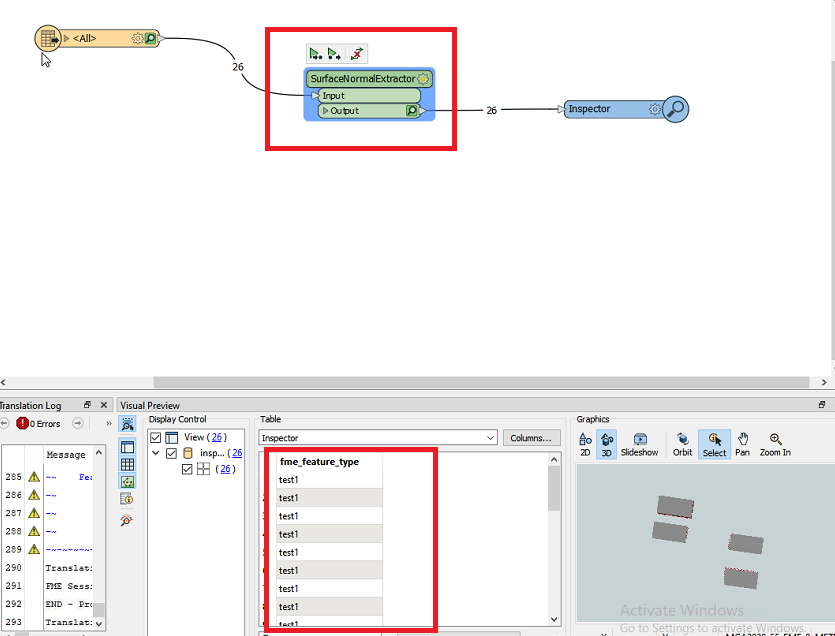
1) How do i ensure, that exterior rings are counter-clockwise, and interior rings are clockwise? I am using the Orientor Transformer, and setting Let-Hand-Rule, however, on surfaces, i still see (from using Inspector against the CityGML) that the polygon is right-hand rule.

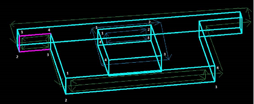
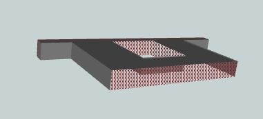
2) When viewing the resultant CityGML in Inspector, it is showing the wall surfaces rather strange..... some are rendered as exterior (solid) representation, some have the interior (dashed) representation.

Does it matter that FME represents it in this way? or does it actually mean something? is it related to point1? These are shown as right hand rule (i want left hand rule).

Thanks,

Steve

icon

Best answer by daveatsafe 22 September 2017, 19:52

View original

8 replies

Userlevel 2
Badge +17

Hi @steveway,

The Orienter sets the left/right hand orientation based on a top down view, and is meant primarily for GIS type polygons. The results on a vertical face like those found in walls may be unpredictable.

A better route to test the surface may be to look at their surface normals to ensure they are pointing in the right direction. The surface normal will point out from the front side of the face. I have created the custom transformer SurfaceNormalExtractor on the FME Hub to extract the surface normal to a geometry trait on each face (https://hub.safe.com/transformers/surfacenormalextractor). The GeometryPropertyExtractor can extract these traits to attributes for testing.

The dashed representation is the back side of a single sided surface. You can reverse the surface using the Orientor transformer with an Orientation Type of Reverse. You can convert it to a double sided surface by setting an appearance on both the Front and Back side with an AppearanceSetter or GeometryColorSetter transformer. However, many 3D viewers do not care if the surface is single sided, and will happily render both sides.

Badge

Hi @steveway,

The Orienter sets the left/right hand orientation based on a top down view, and is meant primarily for GIS type polygons. The results on a vertical face like those found in walls may be unpredictable.

A better route to test the surface may be to look at their surface normals to ensure they are pointing in the right direction. The surface normal will point out from the front side of the face. I have created the custom transformer SurfaceNormalExtractor on the FME Hub to extract the surface normal to a geometry trait on each face (https://hub.safe.com/transformers/surfacenormalextractor). The GeometryPropertyExtractor can extract these traits to attributes for testing.

The dashed representation is the back side of a single sided surface. You can reverse the surface using the Orientor transformer with an Orientation Type of Reverse. You can convert it to a double sided surface by setting an appearance on both the Front and Back side with an AppearanceSetter or GeometryColorSetter transformer. However, many 3D viewers do not care if the surface is single sided, and will happily render both sides.

Thank you for your detailed response - i guess this is why the orientor works with roofs and ground surfaces, but not walls.


To go into a bit more detail on your approach with wall surfaces, once i use the surface normal extractor, how do i test, and how would i enforce a left-hand-rule on these surfaces?


I have tried using geometrypropertyextractor to get the surface_normal_x , y and z, but this just rejects the features.


Many thanks,


Steve
Badge

Hi Dave,


I have done some more on this, with a couple of examples.


I can confirm that the source DGN has the vertices in the correct order, please see this image, and focus on the front wall, and the left hand wall which is highlighted. The polygons have the correct orientation:


When i run the workbench, and then use inspector on the output CityGML, there is a different representation, the dashed appearance, directly correlates to the orientation of the polygons. if it were consistent, then i could just orientor "reverse", but as it is ok for some, but not others, i cannot use that option:

i use orientor LHR or RHR on roofs and grounds, and this works fine.

For the image above, please ignore the internal walls for now (these are consistent with the DGN polygon orientation). however, you can see, that the front face after fme processing, and the left hand wall have inconsistencies when compared to the DGN above. I can confirm in inspector, that the front face is using clockwise, even though in DGN it is counter-clockwise.

I am not sure what i can do to force the desired behaviour in FME.

Thanks,

steve

Userlevel 2
Badge +17

Hi @steveway,

With a simple model like that, you may have good luck with the SolidBuilder transformer. This will build a Brep Solid from your surfaces, as long as there are no gaps. As part of building the Solid, it reorients all the surfaces to point out. After the SolidBuilder, you can use a GeometryCoercer to convert the solid back to a Composite Surface.

To retain the attributes from each original surface, please convert them to traits with the GeometryPropertySetter before building the solid. After the GeometryCoercer, you can use the GeometryPropertyExtractor to extract the traits back to attributes.

Badge

Hi @steveway,

With a simple model like that, you may have good luck with the SolidBuilder transformer. This will build a Brep Solid from your surfaces, as long as there are no gaps. As part of building the Solid, it reorients all the surfaces to point out. After the SolidBuilder, you can use a GeometryCoercer to convert the solid back to a Composite Surface.

To retain the attributes from each original surface, please convert them to traits with the GeometryPropertySetter before building the solid. After the GeometryCoercer, you can use the GeometryPropertyExtractor to extract the traits back to attributes.

Hi Dave, those are coming out of the SolidBuilder as unused. Also i assume, that these would be executed after the CityGML has been generated?


Can you think of anything specific in the transformation between DGN to CityGML that can fix this?


thanks,


Steve


Badge

Hi @steveway,

With a simple model like that, you may have good luck with the SolidBuilder transformer. This will build a Brep Solid from your surfaces, as long as there are no gaps. As part of building the Solid, it reorients all the surfaces to point out. After the SolidBuilder, you can use a GeometryCoercer to convert the solid back to a Composite Surface.

To retain the attributes from each original surface, please convert them to traits with the GeometryPropertySetter before building the solid. After the GeometryCoercer, you can use the GeometryPropertyExtractor to extract the traits back to attributes.

As per your previous post, i was also able to get the surface normals, but they do not seem to show a pattern that I can consistently test in order to use the orientor to reverse.


i will have a surface with correct orientation, that has negative value normals, but then one with correct orientation that has positive value normals.


If i had something reliable i could test, i would just use the orientor to reverse.


Steve


Badge

Hi @steveway,

The Orienter sets the left/right hand orientation based on a top down view, and is meant primarily for GIS type polygons. The results on a vertical face like those found in walls may be unpredictable.

A better route to test the surface may be to look at their surface normals to ensure they are pointing in the right direction. The surface normal will point out from the front side of the face. I have created the custom transformer SurfaceNormalExtractor on the FME Hub to extract the surface normal to a geometry trait on each face (https://hub.safe.com/transformers/surfacenormalextractor). The GeometryPropertyExtractor can extract these traits to attributes for testing.

The dashed representation is the back side of a single sided surface. You can reverse the surface using the Orientor transformer with an Orientation Type of Reverse. You can convert it to a double sided surface by setting an appearance on both the Front and Back side with an AppearanceSetter or GeometryColorSetter transformer. However, many 3D viewers do not care if the surface is single sided, and will happily render both sides.

Hi Dave, would it easier if i shared with the you DGN?


Thanks,


Steve


Badge +1

Hi @daveatsafe​ 


Since this post created 6 years back, now I am facing similar type of issue where wall was not rendered properly by the FME inspector as it has direction issue. I tried "SurfaceNormalExtractor" as suggested by you in the previous post but I didn't get any information out of the transformer. Please find the screenshot . Could you please help me in this regard.


Note : I am unable to send the shape file as there is no option here


attributemissingWall not render properly in FME inspector


inspector 

Reply