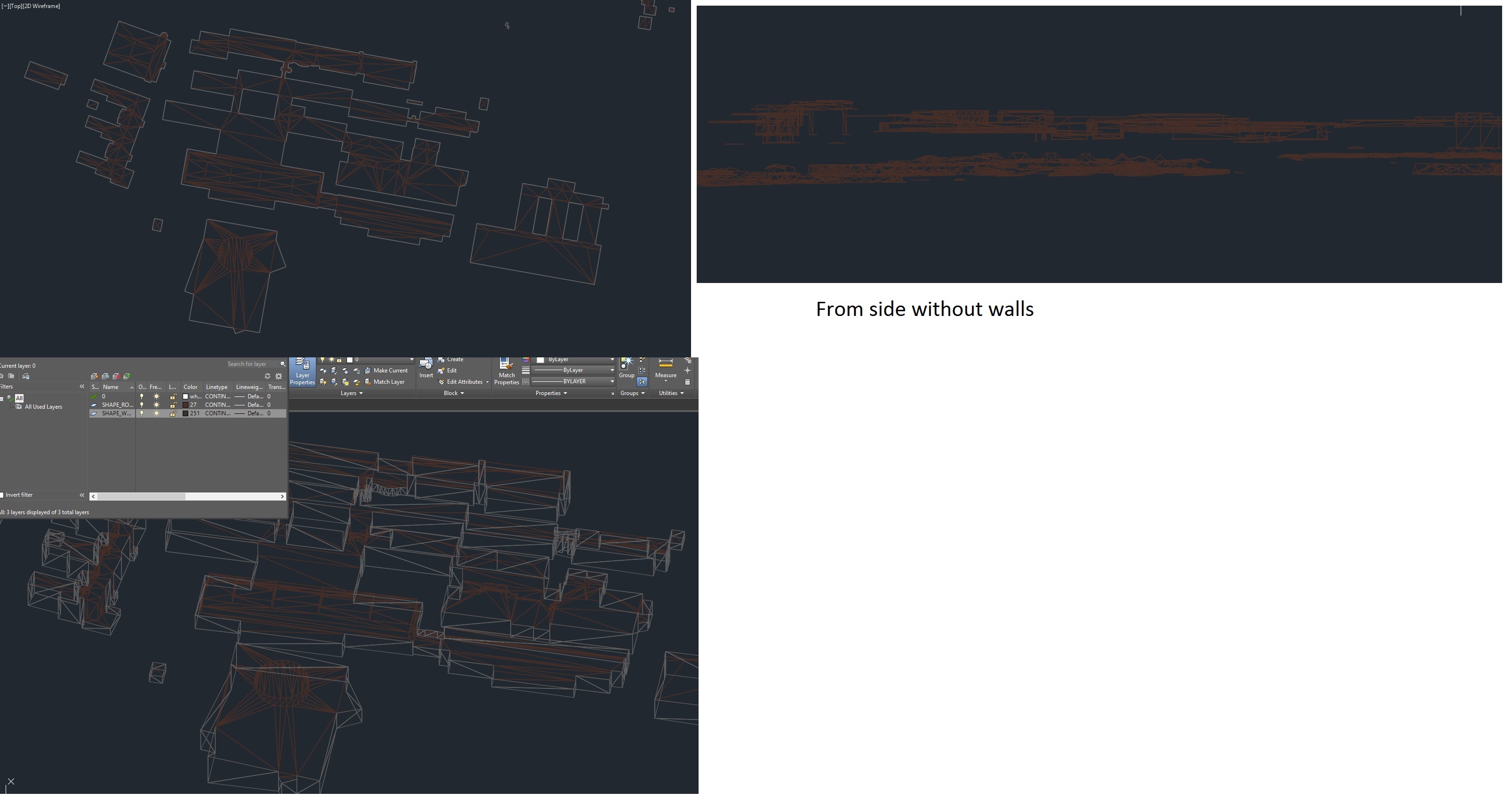
I have Roofs and walls i dwg. But the walls goes 2m to deep in to ground.

Is there any way I can cut the walls with a DTM-raster or TINsurface, or maybe extract new walls from roof to ground.

I would also like to have every building as a solid. The floor dose not have to follow the ground. The floor could be level to the buildings lowest point at ground.

Any ideas?
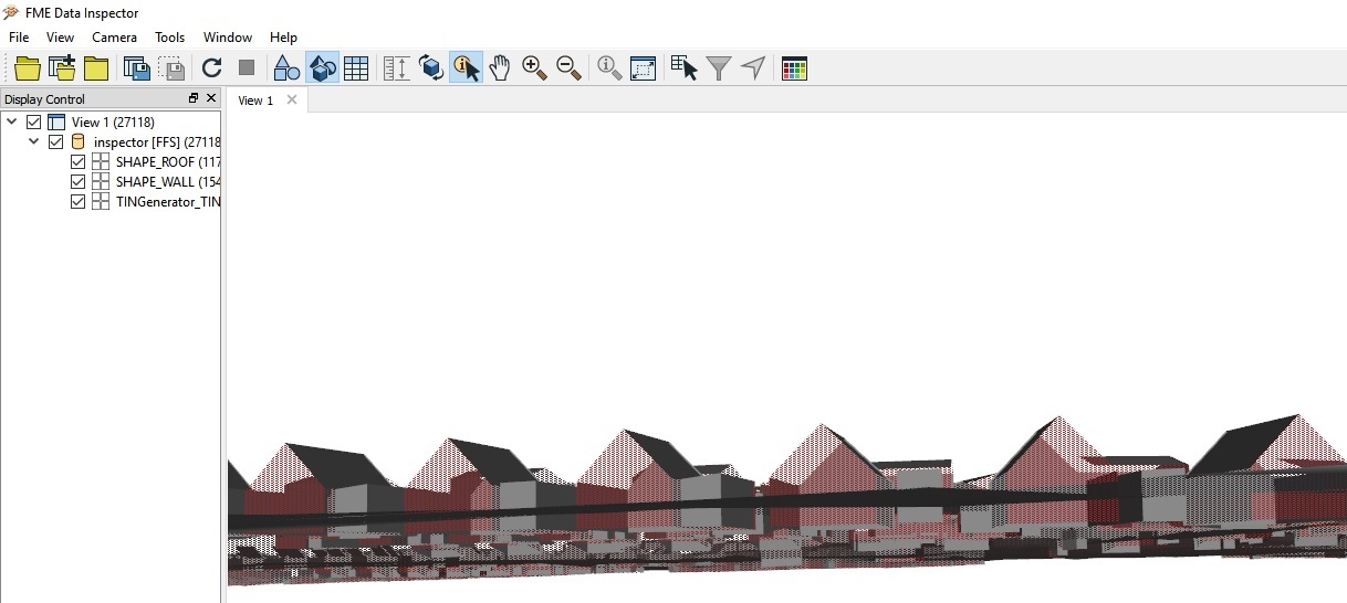
The area in last screenshot is the only buildings with complex roof. All the other buildings are flat, shed or gable.


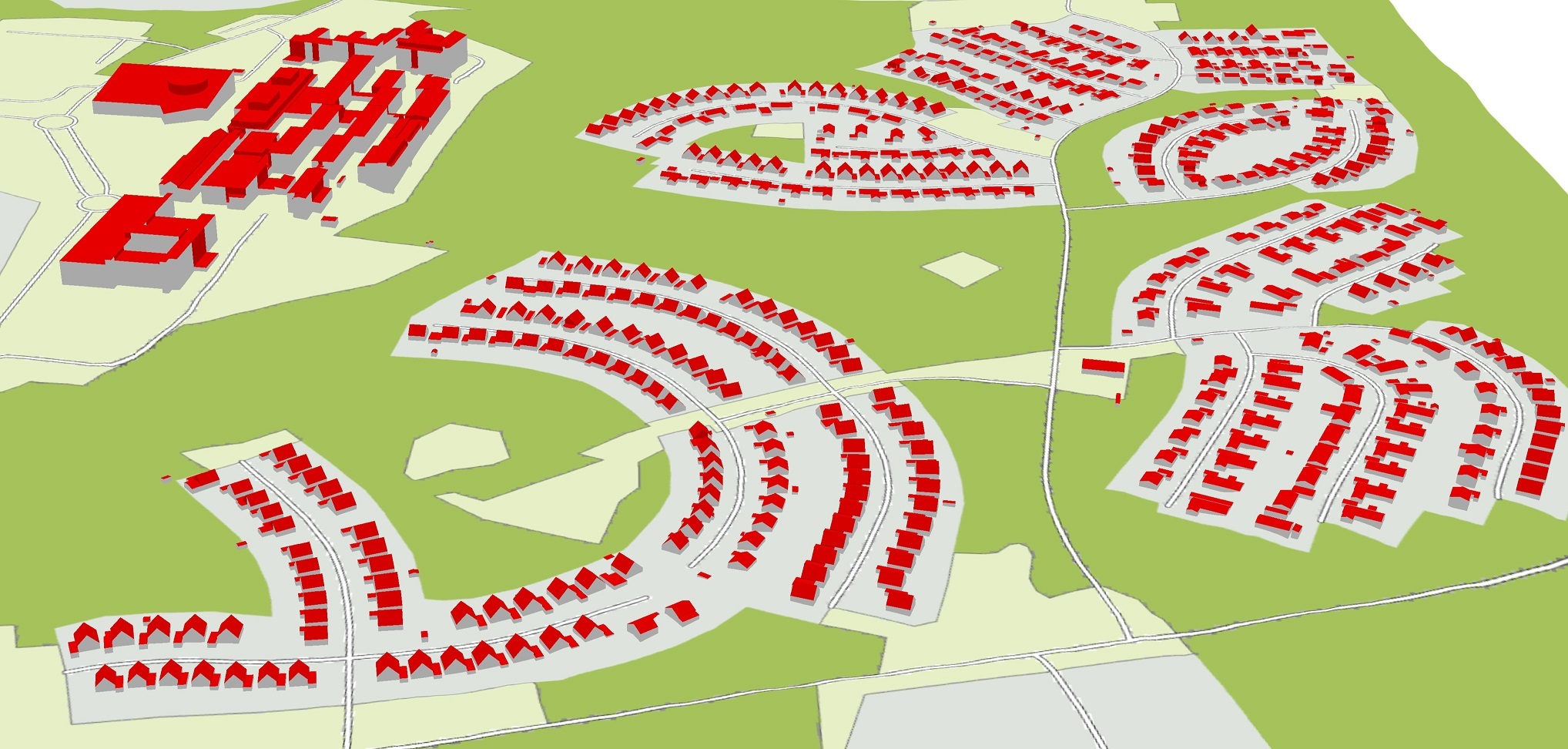
The whole area looks like this:


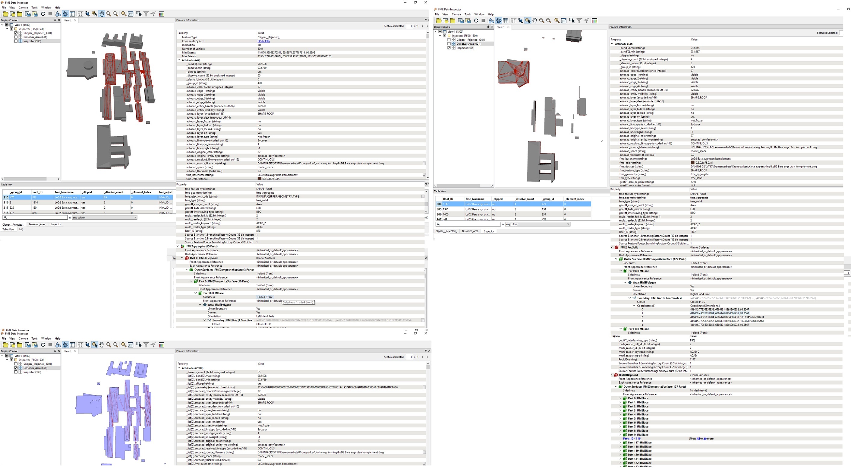
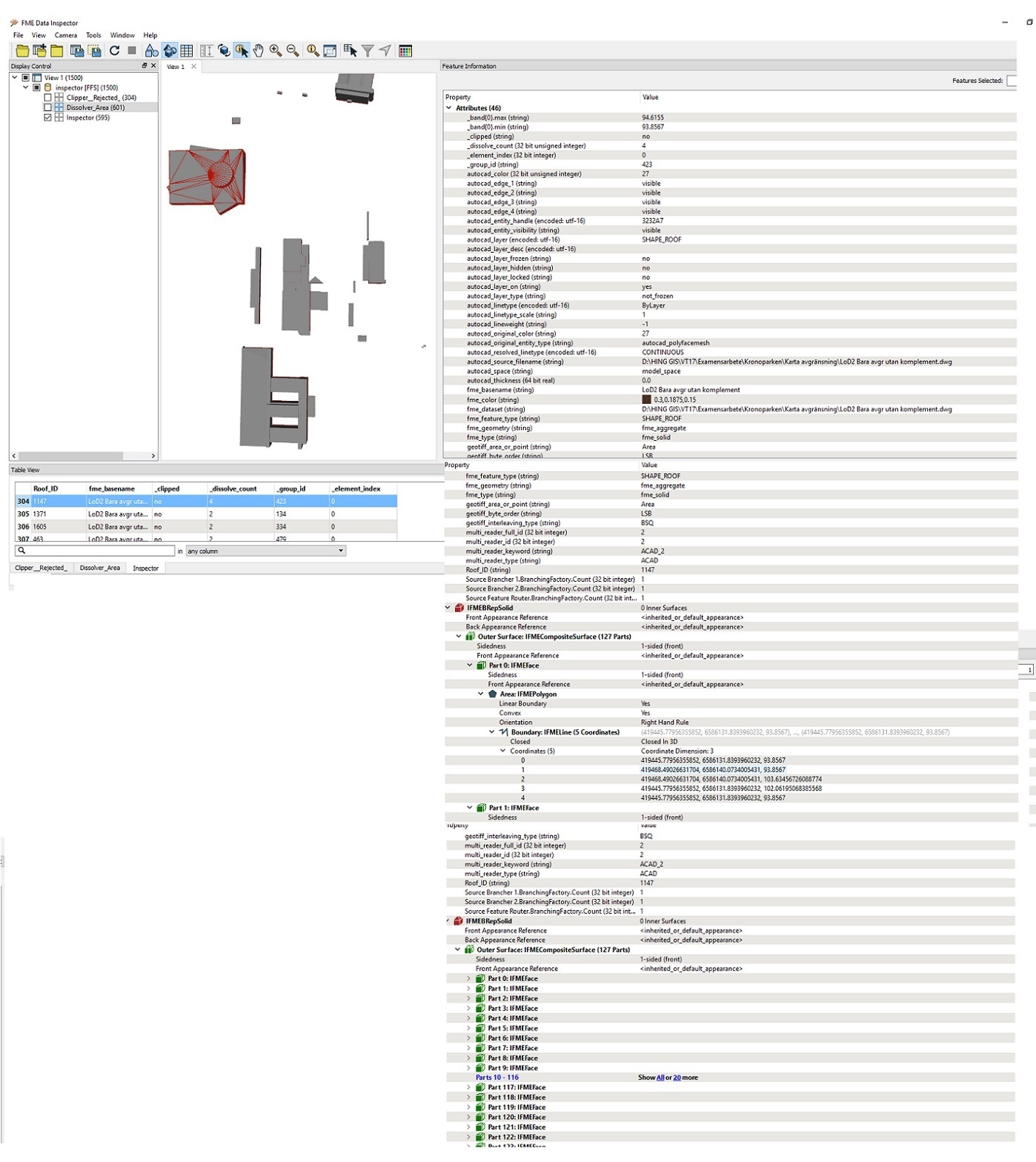
Here is some more data over the complex area. I hope you can see the attributes.


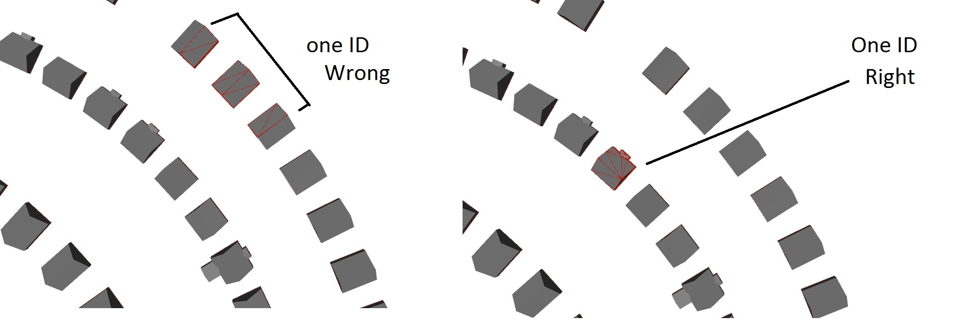
What I want to do is compare this buildings, as I see as "reference" because of low Measurement uncertainty (made by a company) with my buildings i made by myself with LiDAR-data. I have tried to use the spatial filter to transfer attributes based on spatial location. But because (I think) the reference buildings are in segments (see pic below).


The steps 1-8 you showed me first was really helpful because i could run the volume counter and manually count the volume of every segment from one building to get the result (I will use volume to see difference between my buildings and the reference buildings). But to make the reference buildings as solid I think it's easier to automatically count the volumes of every building and compare the based on spatial location.


I just wanted to explain what my goal is with this.


I really appreciate your help.


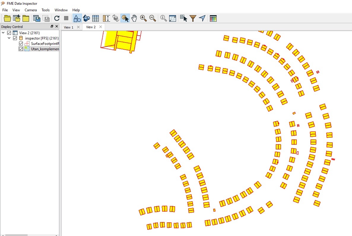
the datasets overlaps almost completely.


Building footprints:


Red outlines=Reference data


Yellow Polygons= made buildings by LiDAR.


I have modified the the data in AutoCAD and ArcGIS and removed all small buildings between the houses, such as garages, sometimes one garage intersects with 2 houses and would be a problem when trying to get a unique ID for every building to relate them to. And later calculate the different in volume between them.


Can you post roof data example including some relatively complex roofs like shown in the last screenshot?


What is the geometry class of the reference solids consisting of multiple segments? If the class was IFMEMultiSolid or IFMECompositeSolid, possibly you could decompose them into individual segment solids with the Deaggregator transformer (Split Composites: Yes).


the datasets overlaps almost completely.


Building footprints:


Red outlines=Reference data


Yellow Polygons= made buildings by LiDAR.


I have modified the the data in AutoCAD and ArcGIS and removed all small buildings between the houses, such as garages, sometimes one garage intersects with 2 houses and would be a problem when trying to get a unique ID for every building to relate them to. And later calculate the different in volume between them.


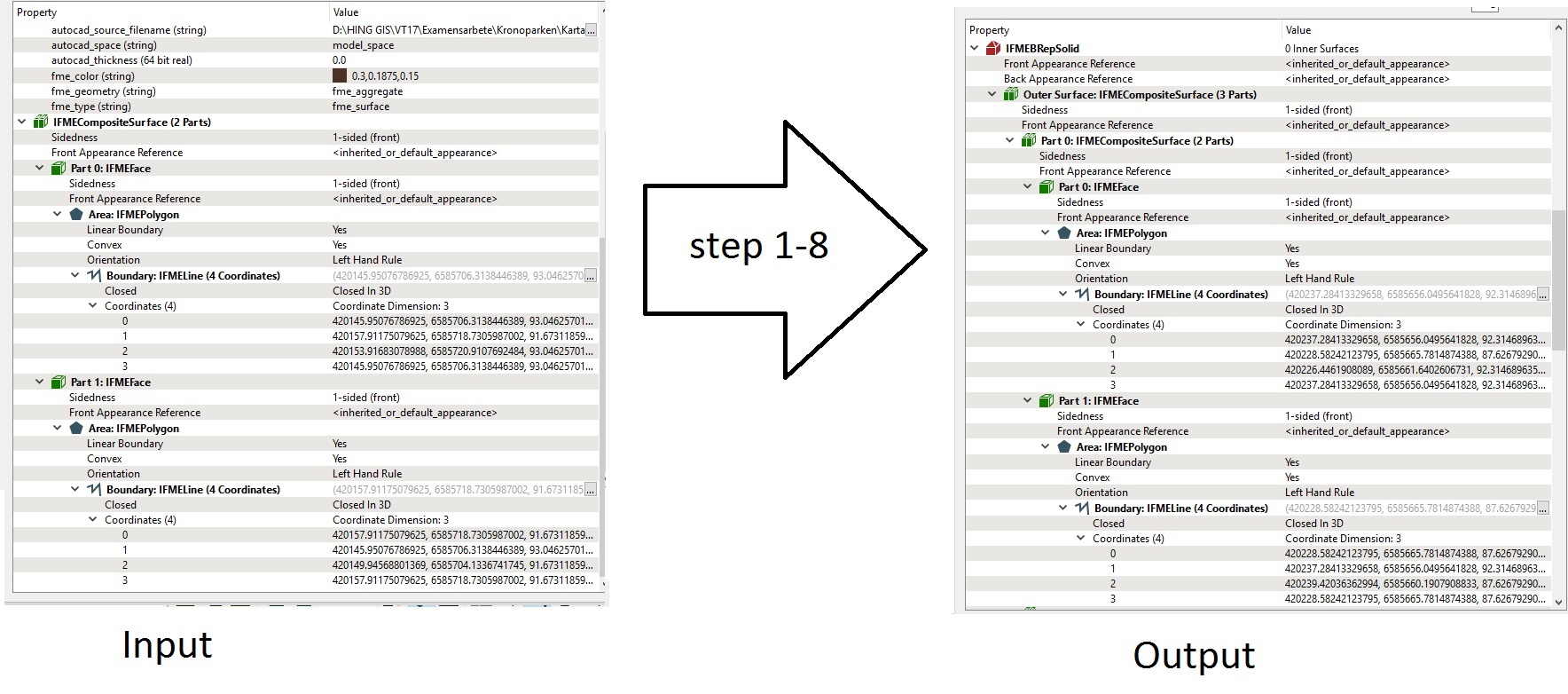
The input roofs in .dwg is IFMECompositeSurface and output after step 1-8 as you showd me is IFMEBRepSolid:


Thanks!


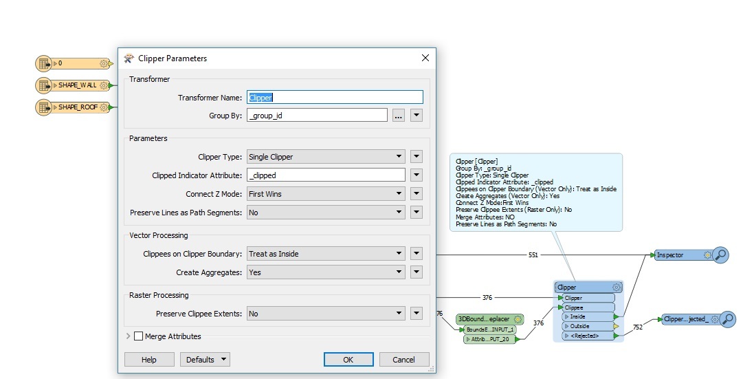
It seems to work except for the clipper. I cant fint the Z and Mesures Parameters.


The rejected clipees says Invalid_Clipper_Geometry_Type


Again.


  • If the roof surfaces in the source dataset which you have to transform into solids don't overlap each other, you can calculate the volume of each building using the output features from the Aggregator in the Step 2.
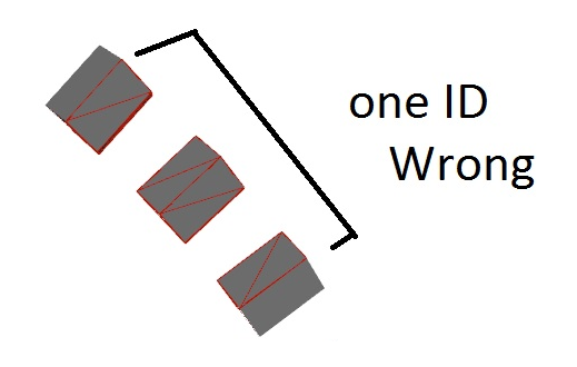
  • What is the geometry class of this "one ID Wrong" feature? Where is this feature come from - the roof surfaces dataset? the reference solids dataset?

If you could post data example, it would help us to understand the conditions correctly.
"wrong" is the output from step 1-8 + spatial filter when i wanted to transfer a House_ID from my buildings made by LiDAR so i can relate each building to each other an see the different in volume. The output is IFMEBRepSolid.


after step 1-8 i could use the VolumeCounter and get the volume. But the buildings was often in two or more parts. I thought that's why i got this "wrong" using SpatialFilter. As you see above the footprints from the two datasets are located at the same spot so an intersect should connect them together.


How can i connect my buildings so buildings from both datasets on the same location gets the same ID so i can calculate the different in volume?


I should have asked that first because i see now that the SpatialFilter does only support area, line and point features.


I think that the aedited]Step 1[/edited] gives the same ID (an attribute called "_group_id") to the solids touching each other.


Again.


  • If the roof surfaces in the source dataset which you have to transform into solids don't overlap each other, you can calculate the volume of each building using the output features from the Aggregator in the Step 2.
  • What is the geometry class of this "one ID Wrong" feature? Where is this feature come from - the roof surfaces dataset? the reference solids dataset?

If you could post data example, it would help us to understand the conditions correctly.
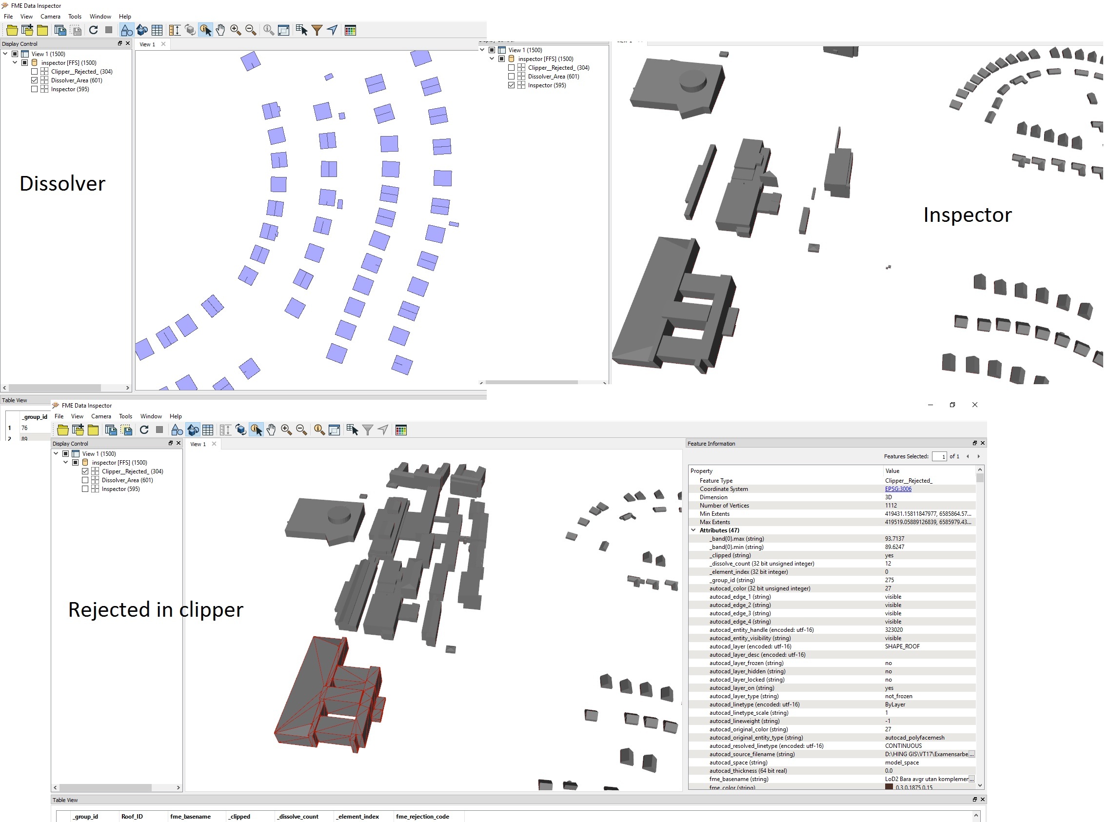
The rejected port in cilpper from part 2 gives me mostly solid buildings but not all. In the Inspector its just some buildings that still are in 2 parts or more.


Maybe the data that becomes solid doesn't touch each other then.


I think that the [edited]Step 1[/edited] gives the same ID (an attribute called "_group_id") to the solids touching each other.


sorry for the typo. The Step 1 does.


Again.


  • If the roof surfaces in the source dataset which you have to transform into solids don't overlap each other, you can calculate the volume of each building using the output features from the Aggregator in the Step 2.
  • What is the geometry class of this "one ID Wrong" feature? Where is this feature come from - the roof surfaces dataset? the reference solids dataset?

If you could post data example, it would help us to understand the conditions correctly.
The Clipper always outputs solid features via the <Rejected> port when the inputs are solid features, though I don't know why. You can just ignore and discard the rejected features in this case.


The issue is that there are some missing parts in the resulting solid (Inspector), but I cannot investigate the reason without actual data.


I ask again finally. Can you post data example including the complex building?


The rejected port in cilpper from part 2 gives me mostly solid buildings but not all. In the Inspector its just some buildings that still are in 2 parts or more.


Maybe the data that becomes solid doesn't touch each other then.


The posts is everywhere now sorry. I posted this before, do you need something else let me know.


The posts is everywhere now sorry. I posted this before, do you need something else let me know.


I will just try to explain may intentions so there is no misunderstanding.


Maybe is this possible after step 1-8?
Again.


  • If the roof surfaces in the source dataset which you have to transform into solids don't overlap each other, you can calculate the volume of each building using the output features from the Aggregator in the Step 2.
  • What is the geometry class of this "one ID Wrong" feature? Where is this feature come from - the roof surfaces dataset? the reference solids dataset?

If you could post data example, it would help us to understand the conditions correctly.
I just need to see actual DWG data containing some sample roof surfaces including the complex one. If you cannot publish any sample data here, consider asking Safe support, sending the actual dataset.


The posts is everywhere now sorry. I posted this before, do you need something else let me know.


From AutoCAD:


Again.


  • If the roof surfaces in the source dataset which you have to transform into solids don't overlap each other, you can calculate the volume of each building using the output features from the Aggregator in the Step 2.
  • What is the geometry class of this "one ID Wrong" feature? Where is this feature come from - the roof surfaces dataset? the reference solids dataset?

If you could post data example, it would help us to understand the conditions correctly.
We need to see the actual data, rather than screenshots. Why not post a sample data?


From AutoCAD:


I don´t have much info about the data itself except that it's mad from stereo mapping.
From AutoCAD:


lod2-to-fme.dwg


Had to remove some buildings to have an excepted file-size.


Again.


  • If the roof surfaces in the source dataset which you have to transform into solids don't overlap each other, you can calculate the volume of each building using the output features from the Aggregator in the Step 2.
  • What is the geometry class of this "one ID Wrong" feature? Where is this feature come from - the roof surfaces dataset? the reference solids dataset?

If you could post data example, it would help us to understand the conditions correctly.
I finally understood the situation. It might be better that the roofs should be aggregated for each building before transforming them to solids.


I think the attached workspace generates better building solids. However, the results may not be perfect since there are slight gaps between some roof surfaces belonging to the same building.


roof-surface-to-building-solid.fmwt (FME 2016.1)


Hope this helps.


lod2-to-fme.dwg


Had to remove some buildings to have an excepted file-size.


It works now.


Thanks a lot!


Reply