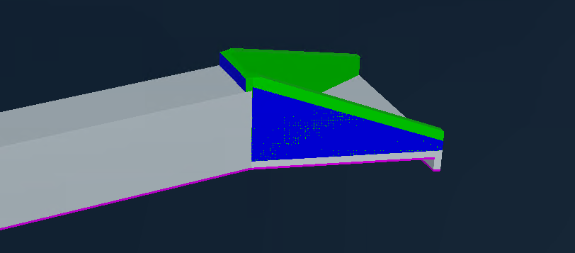
We are producing Cesium 3d Tiles from .dgns, our problem first was that some elements seem to have the wrong surface normals, or so we think and our fix was to use the Orientator transformer, produce a Reversed version of all elements and then Merge these elements back together so we don't have duplicates.


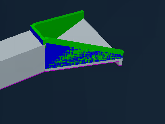
What occured afterwards is that some elements have weird shadings that change as you orbit the element, is there any fix to this? Is this still an issue with the surface normals? Or could it be that some inner color bleeds through because of the normals 'fix' we did?


Thank you in advance!
imageimage

This looks like you have two surfaces on top of each other. The weird shading is caused by Z fighting https://en.wikipedia.org/wiki/Z-fighting

Hard to say if this is a modelling issue or an issue with the conversion process


This looks like you have two surfaces on top of each other. The weird shading is caused by Z fighting https://en.wikipedia.org/wiki/Z-fighting

Hard to say if this is a modelling issue or an issue with the conversion process

Wow, I did not know that is what it's called. Now I do. Today is a good learning day for me!


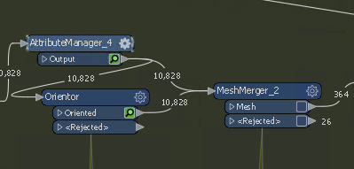
We actually do have two surfaces but that was a workaround for the normals issue, is there a way to merge these back together? What I tried was to use a MeshMerger but It's behaving strange, it gets an input of 20k element IDs, where there are 2 pairs for each ID (I mesh merge by grouping by ID), so it should output 10k and it outputs 300 and rejects 26, the rest of it just disappears

image

Incorrect surface orientation is a real issue, especially when you can't output double sided surfaces. This is the case here. While 3DTiles does support double-sided surfaces it seems that FME never outputs double sided surfaces.

For reference you can see here that gltf 2.0 (the geometry part of 3DTiles) has double sided support

https://www.khronos.org/registry/glTF/specs/2.0/glTF-2.0.html#double-sided


The best fix in your situation is to identify and fix only the incorrectly oriented surfaces - it sucks but it is one of the only ways.

This is a real challenge when reading data which hasn't been properly modelled.


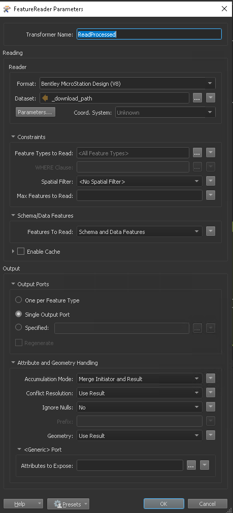
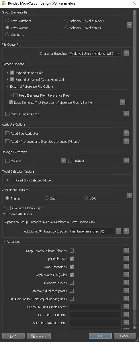
The models are coming from .dgns could it be that the FeatureReader messes Orientation up?

These are my settings:

imageimageIf Im inspecting the source with FME Inspector/Bentley the .dgn files seem fine


The models are coming from .dgns could it be that the FeatureReader messes Orientation up?

These are my settings:

imageimageIf Im inspecting the source with FME Inspector/Bentley the .dgn files seem fine

You can try the Geometry Validator here - set it to fix incorrect Surface Orientation. In order for this to work properly it's best when the data are either a Solid or a Composite Surface.

This process doesn't work if the surfaces are not connected in some way


The problem comes when the input data are polygons or vertical surfaces where it's not clear which way is the correct orientation. This problem is really annoying when working with vector data

Will try that, thank you very much for making things clear!


You can try the Geometry Validator here - set it to fix incorrect Surface Orientation. In order for this to work properly it's best when the data are either a Solid or a Composite Surface.

This process doesn't work if the surfaces are not connected in some way


The problem comes when the input data are polygons or vertical surfaces where it's not clear which way is the correct orientation. This problem is really annoying when working with vector data

I hate the problem - it's painful


Reply