I have a network that is just input lines from shapefiles.
All line ends are snapped together correctly. The network has an origin point that is a point feature shapefile.
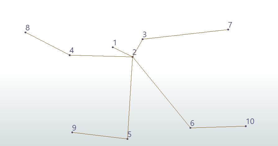
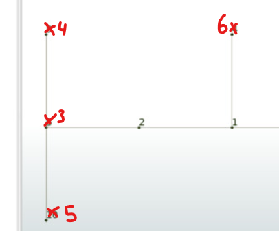
I want to be able to run the TopologyBuilder and assign that origin point as node 1. From there, each subsequent intersection of the lines where a new node is created should be incremental from the origin Node 1.
In my attached picture you can see the top part of the image is what I want. The bottom section of the image is what comes out.
In the TopologyBuilder I am using end nodes only, so there is no overlapping intersections creating false nodes.
I have tried to plug the network into the NetworkFlowOrientor and it does not do anything if I then rebuild the topology after it.
Does anyone have any ideas as to what could be causing this, or how to set an origin node to build a topology on?
*As a side note, I can identify the origin node ID and from there each line segment has the from and to, however I do not know how to order the results using the from and to attributes given that are out of order. Any suggestions on this as well?
For instance, if the origin node is 5, and a line segment is from 5 to 1, and then the next line segment should be from 1 to 2.
Cheers,


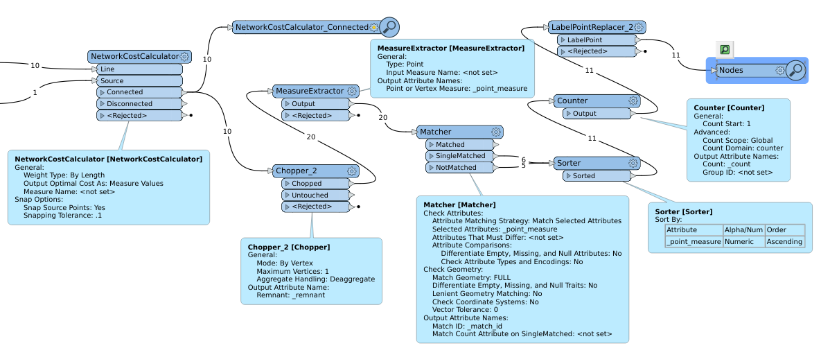 which produces
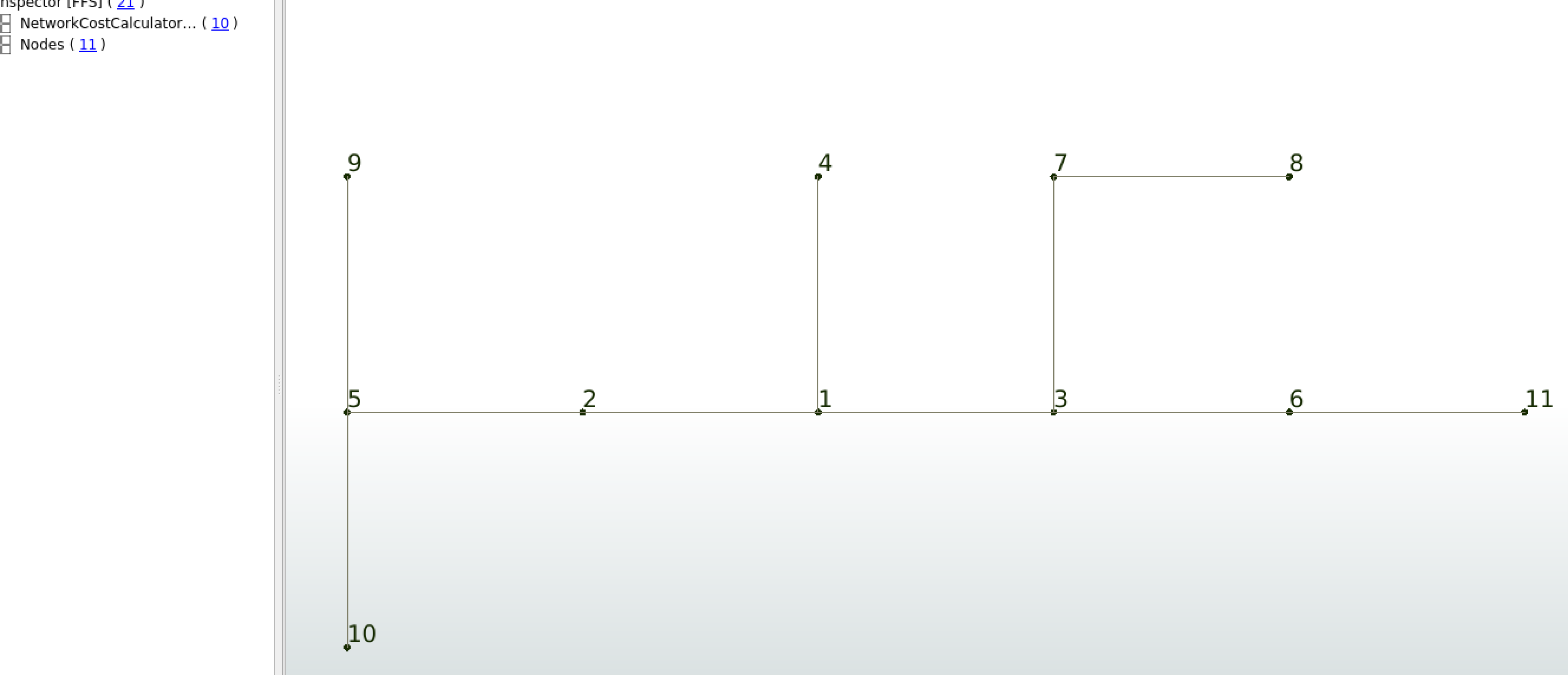
 Or if that is not possible, a way to order the edges based on the from and to. Taking your output the records would look like this: