Question

DWG > GDB projection fails on annotation - coordinates out of range


Hello,


I'm stuck on trying to transform attributes in a DWG to a GDB , and am encountering a projection error. This is specifically for the DWG's annotation/text - the line and area geometry is successful. The projection is from Perth Coastal Grid 1994 (PCG94) projection to WGS1984 Web Mercator Auxillary Sphere (EPSG:3857). The error messages are below:


Reprojector: Reprojection failed

Reproject: Failed to reproject these attribute pairs: autocad_alignment_x / autocad_alignment_y

EsriReprojector_4: Reproject: Could not reproject the geometry of the preceding feature: Reprojector: Could not reproject feature from `_FME_1' to `_SPHERICAL_MERCATOR_0'. Coordinates out of range


cad2gdb 

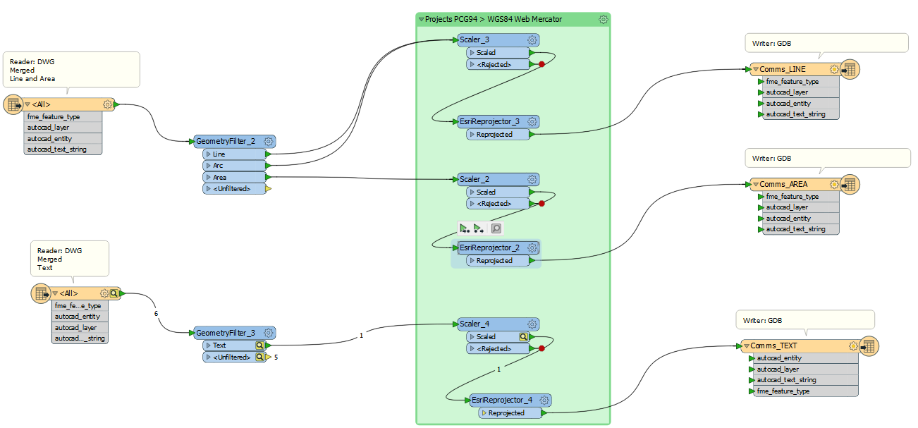
I've separated out the line/area and text geometries to test the success of each. I've tried using the 2DForcer to no avail. I've also tried using a Tester to filter out potential 'problem' annotation layers but every single one is getting caught. I'm aware of Csmapprojector, however PCG94 is not on there, only PCG20.


The scaler is there to set the scale factors at 0.001 as PCG94 operates in milimeters.


I'm using FME Workbench 2018.1 if that helps.


2 replies

Badge +20

When reprojecting via a grid shift method you have to make sure your coordinates are inside of the grid. The minimum "inside" distance is 2 rows/columns in the grid as most reprojections require 16 neighbor points for spline interpolation..

When I began using FME I had to define a custom reprojection method for CSMAPReprojector by adding a few lines to MyCoordSysDefs.fme (C:\Program Files\FME\Reproject):

XFORM_DEF Stereo70_to_ETRS89_NTV2 \
    SRC_DTM Pulkovo42/58b \
    TRG_DTM WGS84 \
    DESC_NM "Stereo 70 to ETRS89 using grid shift file generated from TransDatRo grid" \
    GROUP EUROPE \
    INVERSE Yes \
    METHOD GRID_INTERP \
    GRID_FILE NTv2,fwd,.\GridData\Romania\stereo70_etrs89A.gsb \
    FALLBACK Pulkovo42/58b_to_WGS84

As you can see, I assigned a fallback reprojection method for points outside of the grid.

From what you said above, PCG94 is in millimeters. Make sure Scaler affects al features. autocad_alignment_x / autocad_alignment_y are insertion point attributes of autocad_text features. Check if autocad_alignment_x / autocad_alignment_y are updated by Scaler and if not use Offseter to move features from original position to the new reprojected one OR update them with the reprojected coordinates.

Thanks for the reply, I will attempt to define a custom reprojection method. How do you find/make a grid shift file (gsb) for the PCG94 > WGS84 reprojection? Also how do you know what the proper projection names are under SRC_DTM and TRG_DTM? Not sure how to obtain all the attributes for the fallback method.

The autocad_alignment_x / autocad_alignment_y were indeed scaled.

Reply