
As an ex-land surveyor, I know how useful it is to have data in a local coordinate system. If I'm working on a construction project site, I'll likely have a local grid instead of a UTM zone - and I certainly won't be using latitude and longitude.
So let's see how I can handle that sort of thing in FME...
The CommonLocalReprojector Transformer
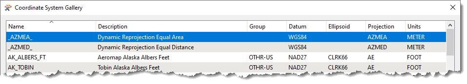
One technology available to us in FME is a "dynamic coordinate system." What that means is FME automatically generates a coordinate system based on the input. The Reprojector transformer can be set to write to a dynamic coordinate system:
But in that case each feature gets its own coordinate system. What we want here is a grid that covers all features. The CommonLocalReprojector will do that for us. Here is an example of its output:
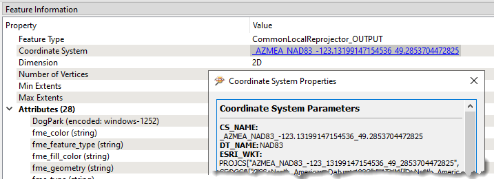
You can see that a local, dynamic coordinate system is added for this feature, and is common to all features. I can even click on the link to see the projection definition.
Local Origin Point
The CommonLocalReprojector works by selecting the centre point of the data and using that as the origin point for a new coordinate system. You can see why the centre point is chosen: it minimizes distortion across the data and equalizes that distortion in all directions.
But... this means I end up with negative coordinates in the left-hand side of my data; and negative coordinates are a bit harder to use in the field. How do I fix that?
One way would be to use the Offsetter transformer to shift the data. But then the coordinate system is not correct because its origin no longer matches the data's origin.
Instead I came up with the idea of tricking the transformer by extending the data, so that 0,0 is now the bottom-left:
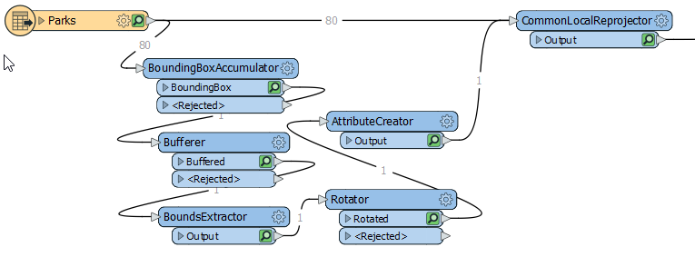
Basically I create a bounding box and then rotate it 180 degrees around the bottom-left point to give me this:

That gives me the result I want in the CommonLocalReprojector, and then I can delete the excess bounding box. I'm simply fooling the transformer into picking the lower-left of the actual data as the centre. But while that works, any distortion is not equal, it's spread to the right of my data, which isn't as good (though it may be good enough).
What I really want is to apply a false easting and northing to my coordinate system:
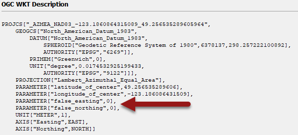
I do that by... well, actually I can't think of a way to do that. The CommonLocalReprojector doesn't have a false origin setting, and if I extract the coordinate system definition and update it, I don't know if I can apply it back to the features.
Summary
OK, that is perhaps a disappointing ending! I can't quite do what I want, although I can do a workaround by tricking FME as to the extents of my data. But I hope that it shows you a little bit about local coordinate systems.
In brief: If you want a local grid for measuring features, then use the Reprojector to go to a dynamic coordinate system; this minimizes overall distortion by giving a separate coordinate system. In fact the Bufferer transformer even has this built in as a units parameter.
But for a grid local to all features, the CommonLocalReprojector is the way to go... and I'll check with our developers about how to set a false origin.