Solved

Find Line connected ( begin and end )

  • 22 September 2020
  • 6 replies
  • 61 views

Userlevel 4
Badge +30

Hi All,


I'm try to find the best way to analyse the begin and end of line and check if this line is connected in the both vertices ( begin and end ).


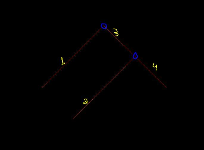
As you can see in image bellow, the line number 3 is connected in the begin and end of the line.

And the others line are not.

Lines_Connected

A DGN file is attached.


Thanks in Advance,

Danilo

icon

Best answer by jdh 22 September 2020, 22:03

View original

6 replies

Badge +22

The way I have done this in the past is a TopologyBuilder (Generate List from Input Edges), on the nodes port test which nodes have only one edge (aka dangle node) based on the number of elements in the edge list (ListElementCounter).


FeatureMerger/FeatureJoiner (x2) the filtered nodes with the lines from the Edge port.

the _node_number of the Node should match either the _from_node or the _to_node of the Edge.

Alternatively the _edgeList{}.fme_arc_id of the Node should match the _edge_id of the Edge (ListBasedFeatureMerger)


The exact way you set it up will depend on whether you want to identify isolated vs dangle, or if the line orientation is important.


Userlevel 4

The way I have done this in the past is a TopologyBuilder (Generate List from Input Edges), on the nodes port test which nodes have only one edge (aka dangle node) based on the number of elements in the edge list (ListElementCounter).


FeatureMerger/FeatureJoiner (x2) the filtered nodes with the lines from the Edge port.

the _node_number of the Node should match either the _from_node or the _to_node of the Edge.

Alternatively the _edgeList{}.fme_arc_id of the Node should match the _edge_id of the Edge (ListBasedFeatureMerger)


The exact way you set it up will depend on whether you want to identify isolated vs dangle, or if the line orientation is important.


Yup, same for me. Works well.

There is also the MRF2DDangleRemover, but it's an extra-cost 3rd party license so it's probably not available to most FME users.

Userlevel 4
Badge +30

The way I have done this in the past is a TopologyBuilder (Generate List from Input Edges), on the nodes port test which nodes have only one edge (aka dangle node) based on the number of elements in the edge list (ListElementCounter).


FeatureMerger/FeatureJoiner (x2) the filtered nodes with the lines from the Edge port.

the _node_number of the Node should match either the _from_node or the _to_node of the Edge.

Alternatively the _edgeList{}.fme_arc_id of the Node should match the _edge_id of the Edge (ListBasedFeatureMerger)


The exact way you set it up will depend on whether you want to identify isolated vs dangle, or if the line orientation is important.


Hi @jdh​ 

This sequence of transformer was formidable. Thanks your help!

Danilo

Userlevel 4
Badge +30

Yup, same for me. Works well.

There is also the MRF2DDangleRemover, but it's an extra-cost 3rd party license so it's probably not available to most FME users.

Thanks @david_r​ This a interesting tip.

Badge +1

Hi jdh, can you post a screenshot of the TopologyBuilder settings for this?

Badge +22

Hi jdh, can you post a screenshot of the TopologyBuilder settings for this?

TopologyBuillder
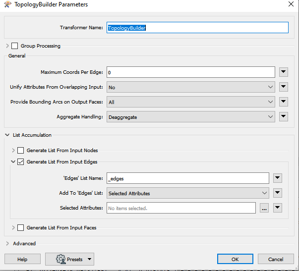
You can add additional attributes, but it is not strictly needed. The _edges list will contain fme_arc_angle, fme_arc_id and fme_direction in additional to whatever attributes you select.


Use the ListElementCounter to get the number of edges on the node, if it's only 1, then it's a dangle node.

Reply