Question

Defining roof shapes without TIN / defining roof planes

  • 20 February 2017
  • 6 replies
  • 24 views

Hi,

I'm trying to work out a way to build simple 3D roof shapes for buildings that creates the minimal number of surfaces in the resulting 3D representation. My input data is a 2D set of building footprints and I have a height attribute per feature. Many of the footprint shapes are rectangular, so adding a minimally complex hipped or gable type shape on top of an extruded block of the building will likely be sufficient. My first attempt to create a roof was to use a triangulation based approach:

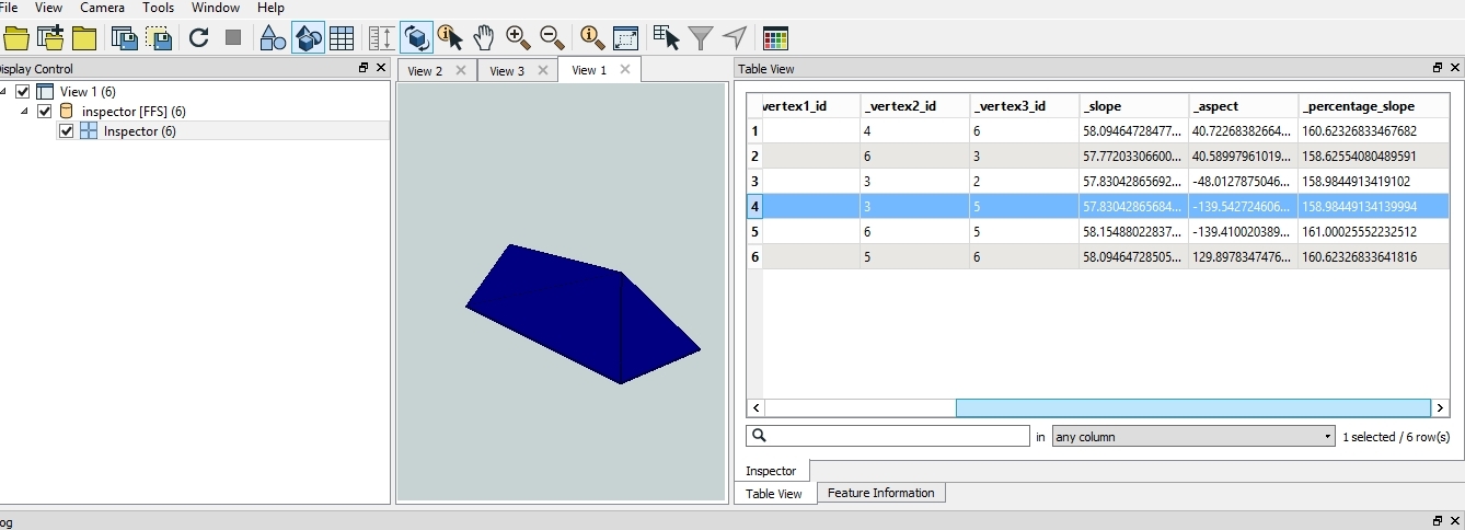
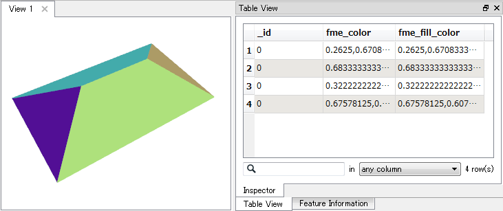
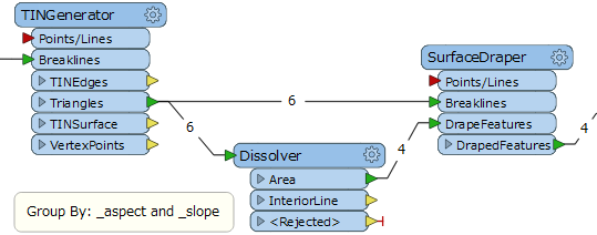
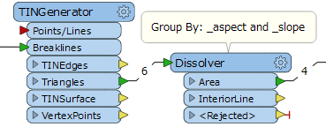
Input footprints -> 3DOffset (by height attribute) -> CenterLineReplacer -> TINGenerator (centre line and footprint to "breaklines" input) -> GeometryExtractor (from Triangles output).

This is OK and does create a hipped shape (see image), but the problem is I want to minimise the number of surfaces. This approach creates 6 triangles for this rectangle example - 2 end triangles, then 2 triangles for each of the long surfaces (there is no surface at the underneath the hipped shape). I think the long surfaces should be actually be 1 surface each as would be achieved my merging the (almost) planar triangles. Presumably this could be done by doing some rounding of the aspect values and then dissolving on this attribute. But that seems unnecessarily complicated.

So, can I actually create the hipped surface without a triangulation step? The Straight Skeleton of the CentreLineReplacer identifies a 2D line that looks like it be modified to create the 3D polygons directly. But how can I define the 3D planes / 3D faces? I thought maybe I could merge straight skeleton and footprint and then assign the Z values of the polygon edges that are the centre line - but what transformer would do this?

any advice much appreciated.


6 replies

Badge +16
Hi, not sure about your questions but wanted to point out this question, hopefully some of the answers help.


https://knowledge.safe.com/questions/38825/how-to-create-a-mansard-roof-from-a-top-and-bottom.html


Userlevel 2
Badge +17

Hi @3dmodeller, if I understand your requirement correctly, a possible way is:

  1. Branch the data flow into two streams.
  2. On the first stream, performs the same transformation as your workflow to create the TIN surface, but replace the TINGenerator with a SurfaceDraper.
  3. On the second stream, create 2D polygons as the seed of expected four surfaces, and send them to the DrapeFeatures port of the SurfaceDraper.
  4. Then, the SurfaceDraper will output 3D polygons representing four surfaces of a hip roof like this.

To create the 2D polygons in the step 3: Send the original footprint (rectangular polygon) and its center line feature created by the CenterLineReplacer (Mode: Straight Skeleton) to the Chopper (Mode: By Vertex, Maximum Vertices: 2). You can then create the polygons with the AreaBuilder from the chopped line segments.

If you need to transform the four 3D polygons into a single surface geometry, a post process consisting of these transformers in a series might help you: Orientor (Orientation Type: Left hand rule) -> FaceReplacer -> Aggregator -> GeometryCoercer (Geometry Type: fme_composite_surface)

This workflow might work too, and it seems to close to your first thought. It might be better to round the _slope and _aspect attribute values before dissolving in order to absorb computational error, as you mentioned.


The data flow is simple, but feel something redundant since the same surface modelling is performed twice with the TINGenerator and the SurfaceDraper.


Userlevel 2
Badge +17

Hi @3dmodeller, if I understand your requirement correctly, a possible way is:

  1. Branch the data flow into two streams.
  2. On the first stream, performs the same transformation as your workflow to create the TIN surface, but replace the TINGenerator with a SurfaceDraper.
  3. On the second stream, create 2D polygons as the seed of expected four surfaces, and send them to the DrapeFeatures port of the SurfaceDraper.
  4. Then, the SurfaceDraper will output 3D polygons representing four surfaces of a hip roof like this.

To create the 2D polygons in the step 3: Send the original footprint (rectangular polygon) and its center line feature created by the CenterLineReplacer (Mode: Straight Skeleton) to the Chopper (Mode: By Vertex, Maximum Vertices: 2). You can then create the polygons with the AreaBuilder from the chopped line segments.

If you need to transform the four 3D polygons into a single surface geometry, a post process consisting of these transformers in a series might help you: Orientor (Orientation Type: Left hand rule) -> FaceReplacer -> Aggregator -> GeometryCoercer (Geometry Type: fme_composite_surface)

Don't worry, the SurfaceDraper can be removed from the previous workflow. You can control how z-coordinates should be handled in the Dissolver through a parameter called "Connect Z Mode".


Userlevel 2
Badge +17

Oh, the question was "can I actually create the hipped surface without a triangulation step?". I didn't have answered to the question yet.

I think there is no easy way to construct the required 3D polygons without a triangulation step. Even if it was possible, it could be a complicated workflow and also the performance might not be better than a workflow containing a triangulation process.

Triangulation is a well known algorithm and I believe that it has been optimized in the FME implementation, so I think the workflows I suggested above are not so bad. However, if you don't want to use a triangulation step anyway, Python scripting might be a next-best choice.

[Addition] For example:

# PythonCaller Script Example:
# Create 3D Polygons representing a Hip Roof surfaces
# The input feature should have a rectangular polygon geometry
# and these two attributes:
# "_elevation": elevation of the bottom of the roof
# "_roof_hight": the hight between the bottom and top of the roof
# Otherwise this script doesn't work and possibly raises an error.
from fmeobjects import FMELine, FMEPolygon
import math
class HipRoofCreator(object):
    def input(self,feature):
        el = float(feature.getAttribute('_elevation'))
        rh = float(feature.getAttribute('_roof_height'))
        
        # Get coordinates of the four corners of the input rectangle.
        line = feature.getGeometry().getBoundaryAsCurve()
        line.force3D(el)
        p = [point.getXYZ() for point in line.getPoints()[:-1]]
        
        # Calculate the lengths of the first and second side of the rectangle.
        # If the first side is longer than the second side,
        # re-order the coordinates list so that the first side will be shorter.
        len1 = math.hypot((p[1][0]-p[0][0]), (p[1][1]-p[0][1]))
        len2 = math.hypot((p[2][0]-p[1][0]), (p[2][1]-p[1][1]))
        if len2 < len1:
            p = p[1:] + [p[0]]

        # Compute a vector (vx, vy) directed along the longer side
        # and having a half length of the shorter side.     
        longer, shorter = max(len1, len2), min(len1, len2)
        vx = (p[2][0]-p[1][0])/longer * shorter * 0.5
        vy = (p[2][1]-p[1][1])/longer * shorter * 0.5
        
        # Compute coordinates of the two tops of the roof.
        z = el + rh
        q0 = ((p[0][0]+p[1][0])*0.5 + vx, (p[0][1]+p[1][1])*0.5 + vy, z)
        q1 = ((p[2][0]+p[3][0])*0.5 - vx, (p[2][1]+p[3][1])*0.5 - vy, z)
        
        # Create four 3D polygons for each surface of the roof and output them.
        boundaries = [
            [p[0], p[1], q0],
            [p[1], p[2], q1, q0],
            [p[2], p[3], q1],
            [p[3], p[0], q0, q1],
        ]
        for bndry in boundaries:
            bndry.append(bndry[0]) # close the boundary coordinates list
            feature.setGeometry(FMEPolygon(FMELine(bndry)))
            self.pyoutput(feature)

Thank you Takashi! These are great answers and I have got very close to what I intended. Your solution with the SurfaceDraper is actually the most similar to what I was originally thinking. The resulting FME polygons look exactly like I wanted. However, as you rightly guessed I wanted to create a single surface geometry and this is where I do run into the issue of surfaces not always being co-planar, meaning they will be rejected by FaceReplacer and there will be holes in the final single surface.

What I have gone with for the moment is a split workflow where 4 sided buildings use the SurfaceDraper method and buildings with >4 sides use a TIN method with numeric rounding to merge near co-planar faces. In time, I wonder if I can modify to a hybrid approach to use the SurfaceDraper method for the planar parts of the building and fill in the other parts with the TIN approach.


More generally, I think this modelling question is an important and interesting issue. My wish to avoid triangulation wasn't because I think the triangulation algorithm itself is sub-optimal or slow - it's that I want to maximise the rendering performance of the final model and that means reducing number of surfaces / triangles. I guess the reason that some surfaces are not planar is due to small measurement issues errors in real-world coordinate data and also coordinate rounding issues. So this issues starts moving into the space of fitting algorithms (rather than geometry algorithms) that can adjust the 3D position vertices to enforce a planar surface - a feature that would be great to have in FME!

Reply