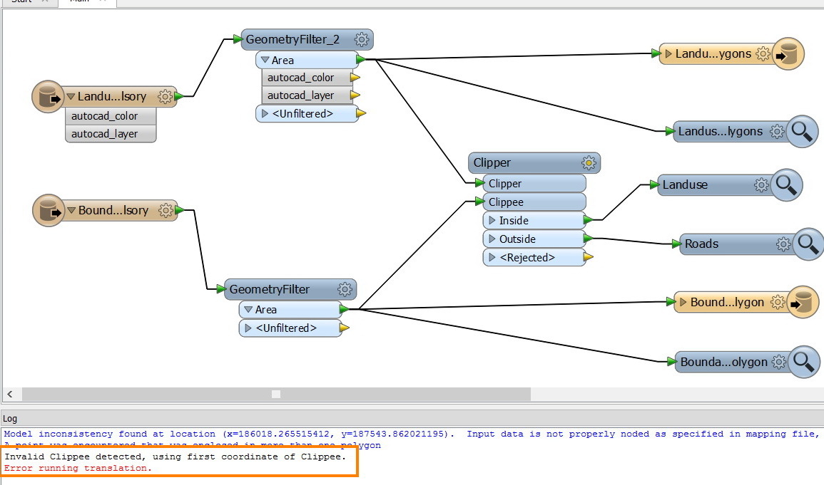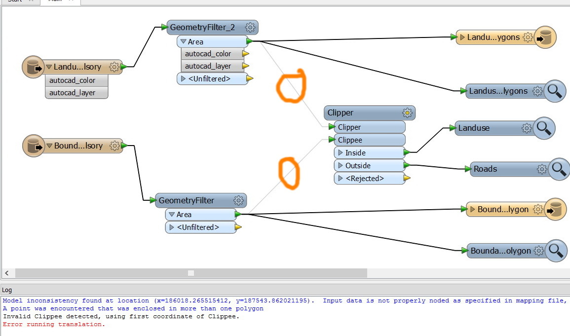

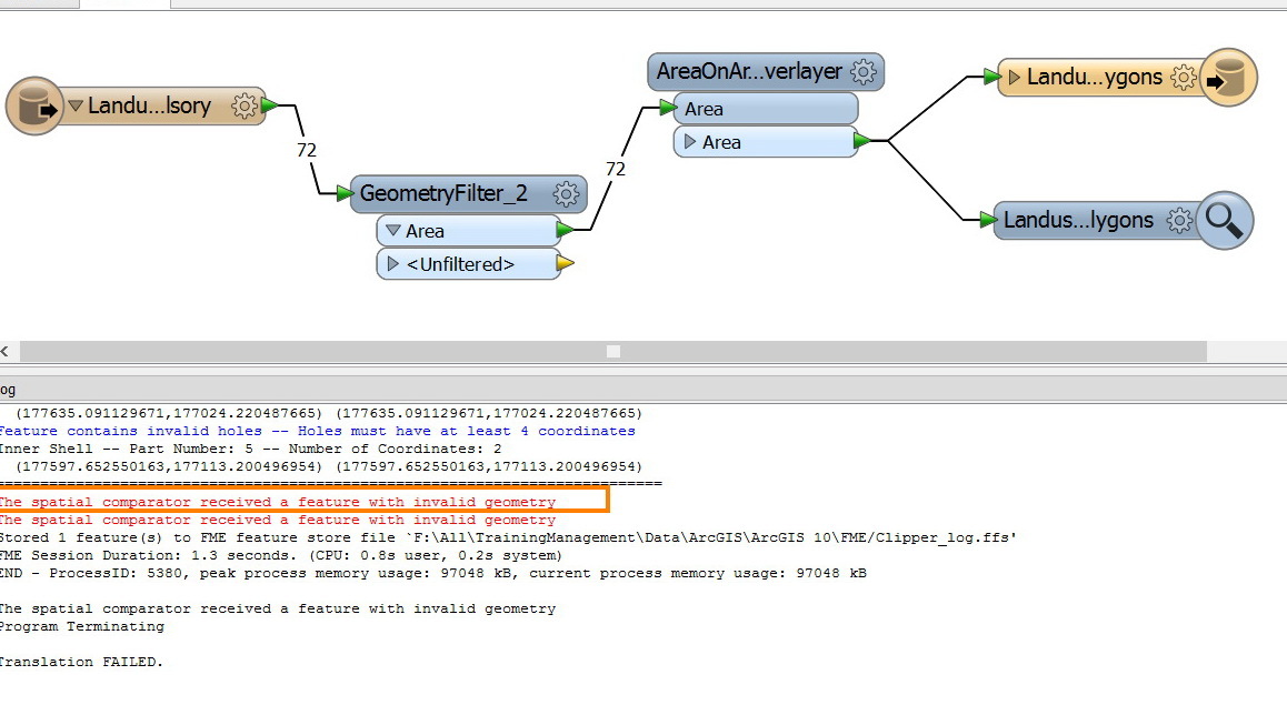
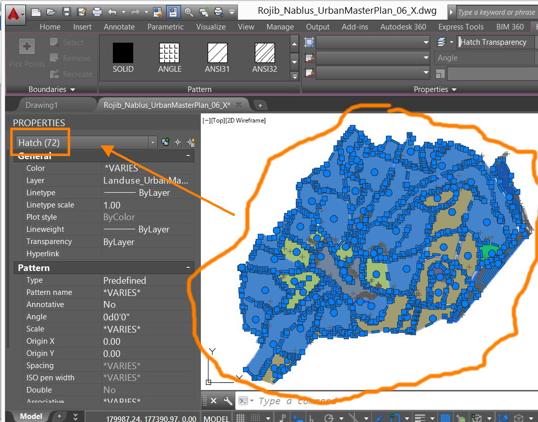
I wanted to apply the “AreaOnAreaOverlayer” on the CAD file below but I got the error below:
“The spatial comparator received a feature with invalid geometry”
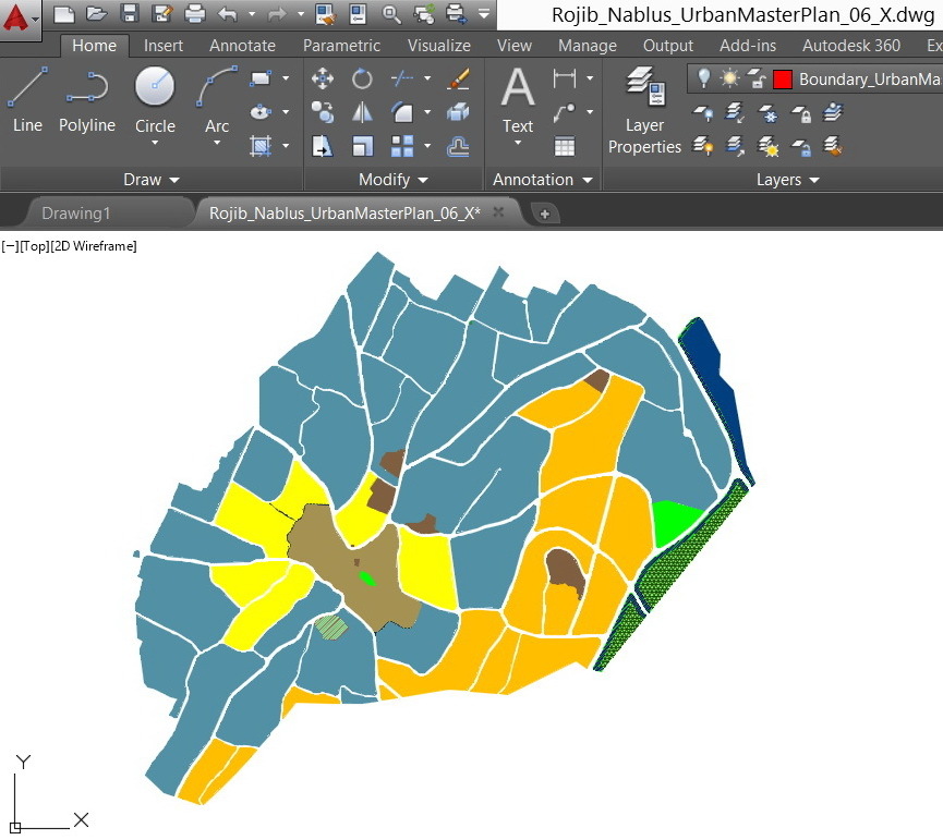
CAD file:
http://www.mediafire.com/download/lf3y6k096nj1724/Rojib_Nablus_UrbanMasterPlan_06_X.dwg
What might be the issue here?
Thank you
Best
Jamal


 Hi Jamal,