
I have a Point Between Two Line , I need to Convert those point into Line of certain lenght


 +8
+8
Maybe you can try the PointConnector.

Userlevel 2
 +17
+17
- Contributor
- 7538 replies
-
1 September 2017

Can you post images to illustrate the original point and two lines, and the required line that should be created from the point?
Hi, @rajibtechlabs. I agree with @takashi - can we please have more information? Is there an ID that you can use to determine which lines to use for each point, or do you want to figure that out spatially? Once you have two lines and a point selected, do you want the new line to be created so that it passes through the point and is perpendicular to the existing lines (as in sample A below)? Or do you want the new line parallel to the existing lines (As in sample B below)? Or something different?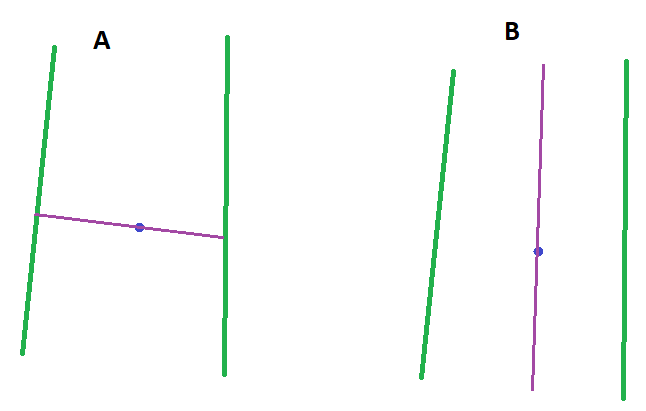
+8
Hi, @rajibtechlabs. I agree with @takashi - can we please have more information? Is there an ID that you can use to determine which lines to use for each point, or do you want to figure that out spatially? Once you have two lines and a point selected, do you want the new line to be created so that it passes through the point and is perpendicular to the existing lines (as in sample A below)? Or do you want the new line parallel to the existing lines (As in sample B below)? Or something different?
Maybe you can try the PointConnector.
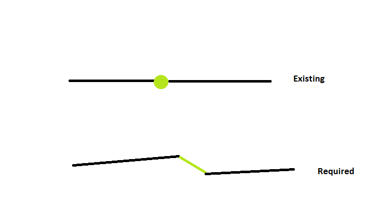 Want to Convert Green Point into Line
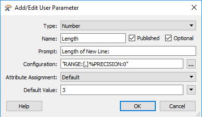
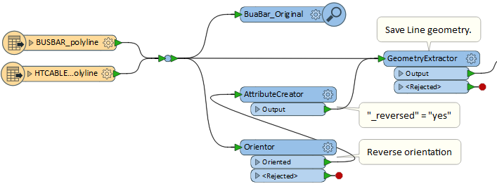
I have created an example workspace for you. In the workspace, ignore the creators - I am just using them to create the 2 original lines and a point in the middle. I have created an numeric user parameter for the length.
Then used an AttributeCreator to calculate the offset using the Pythagorean Theorem. Then offset the point in 2 directions, and used the LineBuilder to connect the points.
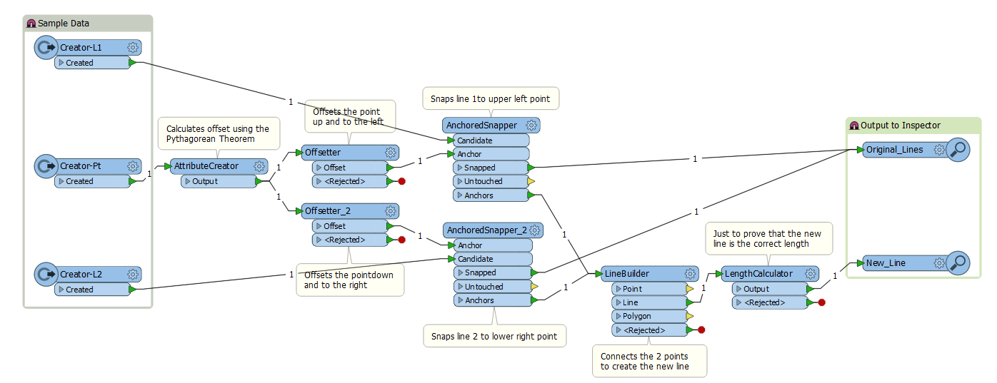
Here is the result!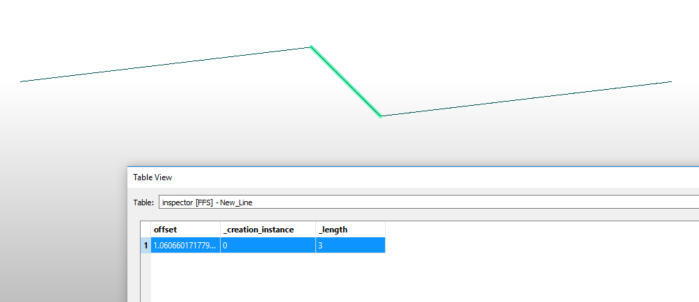
NOTE: This will only work for horizontal lines. You will need to modify it to work for lines with a different orientation.
See attached for the workspace.
-Courtney
I have created an example workspace for you. In the workspace, ignore the creators - I am just using them to create the 2 original lines and a point in the middle. I have created an numeric user parameter for the length.
Then used an AttributeCreator to calculate the offset using the Pythagorean Theorem. Then offset the point in 2 directions, and used the LineBuilder to connect the points.
Here is the result!
NOTE: This will only work for horizontal lines. You will need to modify it to work for lines with a different orientation.
See attached for the workspace.
-Courtney
Thanks @ courtney_m
Your File is working fine , but when i tried with my shape file ,result is nor Coming .Will you please check it wih my shape File is attached
Userlevel 2
+17
- Contributor
- 7538 replies
-
2 September 2017
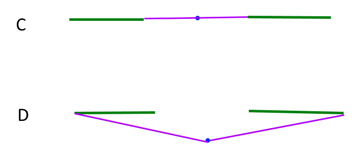
Your image is not enough to illustrate the conditions and requirements, so I try presuming.
- A switch-point touches end nodes of just two bus-bar line.
- Original two bus-bar lines related to the same switch-point are on the same straight line.
- Length of bus-bar lines should not be changed though the processing.
- End nodes of bus-bar lines opposite to switch-point should not be moved through the processing.
In this image, for example, L1 and L2 (gray lines) are the original bus-bar lines, and L1' and L2' (blue lines) are the lines after inserting a switch-line (red line) that has a certain length.
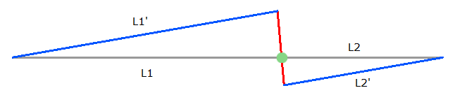
Here, L1 and L2 are on the same straight line, and the lengths of L1' and L2' are the same as L1 and L2 for each.
Have I presumed your requirement exactly?
Your image is not enough to illustrate the conditions and requirements, so I try presuming.
- A switch-point touches end nodes of just two bus-bar line.
- Original two bus-bar lines related to the same switch-point are on the same straight line.
- Length of bus-bar lines should not be changed though the processing.
- End nodes of bus-bar lines opposite to switch-point should not be moved through the processing.
In this image, for example, L1 and L2 (gray lines) are the original bus-bar lines, and L1' and L2' (blue lines) are the lines after inserting a switch-line (red line) that has a certain length.
Here, L1 and L2 are on the same straight line, and the lengths of L1' and L2' are the same as L1 and L2 for each.
Have I presumed your requirement exactly?
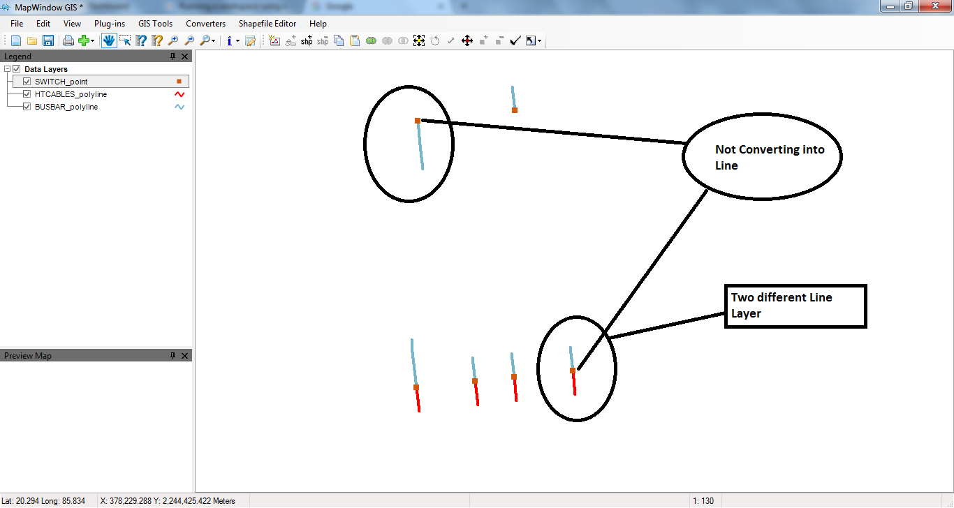
Thanks @takashi workbench is working fine ,but in some case it not working please see in image. sample shape file attached .
Userlevel 2
+17
- Contributor
- 7538 replies
-
4 September 2017
Your image is not enough to illustrate the conditions and requirements, so I try presuming.
- A switch-point touches end nodes of just two bus-bar line.
- Original two bus-bar lines related to the same switch-point are on the same straight line.
- Length of bus-bar lines should not be changed though the processing.
- End nodes of bus-bar lines opposite to switch-point should not be moved through the processing.
In this image, for example, L1 and L2 (gray lines) are the original bus-bar lines, and L1' and L2' (blue lines) are the lines after inserting a switch-line (red line) that has a certain length.
Here, L1 and L2 are on the same straight line, and the lengths of L1' and L2' are the same as L1 and L2 for each.
Have I presumed your requirement exactly?
If a switch-point that matches just one bus-bar should also be transformed into a line, clarify what kind of shape is finally required.
Your image is not enough to illustrate the conditions and requirements, so I try presuming.
- A switch-point touches end nodes of just two bus-bar line.
- Original two bus-bar lines related to the same switch-point are on the same straight line.
- Length of bus-bar lines should not be changed though the processing.
- End nodes of bus-bar lines opposite to switch-point should not be moved through the processing.
In this image, for example, L1 and L2 (gray lines) are the original bus-bar lines, and L1' and L2' (blue lines) are the lines after inserting a switch-line (red line) that has a certain length.
Here, L1 and L2 are on the same straight line, and the lengths of L1' and L2' are the same as L1 and L2 for each.
Have I presumed your requirement exactly?
2) Switch between Two HTCABLE
3) Switch between one busbar and One HTCALBLE
4) Switch connected one side busbar or HTCABLE
Userlevel 2
+17
- Contributor
- 7538 replies
-
4 September 2017
Your image is not enough to illustrate the conditions and requirements, so I try presuming.
- A switch-point touches end nodes of just two bus-bar line.
- Original two bus-bar lines related to the same switch-point are on the same straight line.
- Length of bus-bar lines should not be changed though the processing.
- End nodes of bus-bar lines opposite to switch-point should not be moved through the processing.
In this image, for example, L1 and L2 (gray lines) are the original bus-bar lines, and L1' and L2' (blue lines) are the lines after inserting a switch-line (red line) that has a certain length.
Here, L1 and L2 are on the same straight line, and the lengths of L1' and L2' are the same as L1 and L2 for each.
Have I presumed your requirement exactly?
However, 4) is a completely different condition from others, and you didn't mention any requirement on this condition before. In the case 4), should the switch-point transform into what shape? If you need to create a line segment from the point, should connect between from where to where? Can find no answer unless you specify the requirements exactly.
Your image is not enough to illustrate the conditions and requirements, so I try presuming.
- A switch-point touches end nodes of just two bus-bar line.
- Original two bus-bar lines related to the same switch-point are on the same straight line.
- Length of bus-bar lines should not be changed though the processing.
- End nodes of bus-bar lines opposite to switch-point should not be moved through the processing.
In this image, for example, L1 and L2 (gray lines) are the original bus-bar lines, and L1' and L2' (blue lines) are the lines after inserting a switch-line (red line) that has a certain length.
Here, L1 and L2 are on the same straight line, and the lengths of L1' and L2' are the same as L1 and L2 for each.
Have I presumed your requirement exactly?
1)Switch between Two busbar
2) Switch between Two HTCABLE
3) Switch between one busbar and One HTCALBLE
4) Switch connected one side busbar or HTCABLE
5)Nothing is Connected at both end.
Userlevel 2
+17
- Contributor
- 7538 replies
-
5 September 2017
Your image is not enough to illustrate the conditions and requirements, so I try presuming.
- A switch-point touches end nodes of just two bus-bar line.
- Original two bus-bar lines related to the same switch-point are on the same straight line.
- Length of bus-bar lines should not be changed though the processing.
- End nodes of bus-bar lines opposite to switch-point should not be moved through the processing.
In this image, for example, L1 and L2 (gray lines) are the original bus-bar lines, and L1' and L2' (blue lines) are the lines after inserting a switch-line (red line) that has a certain length.
Here, L1 and L2 are on the same straight line, and the lengths of L1' and L2' are the same as L1 and L2 for each.
Have I presumed your requirement exactly?
However, in the condition 4), it's unclear how the direction of the resulting line should be determined. What is the rule to determine the direction of your desired switch-line, in the condition 4)?
Reply
Enter your username or e-mail address. We'll send you an e-mail with instructions to reset your password.