Solved

Draping polygonal features on a TIN?


Badge

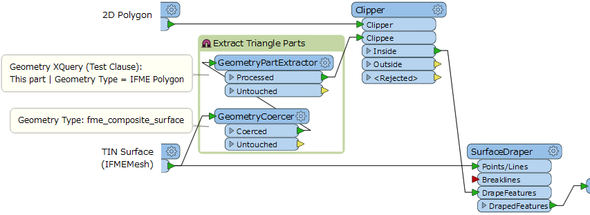
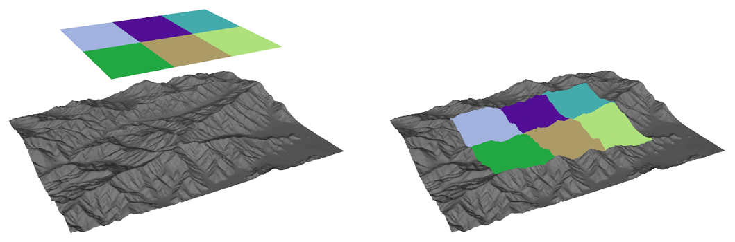
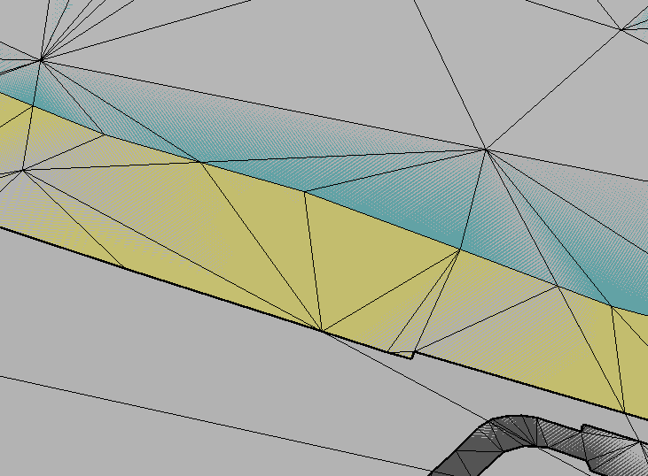
Please I want to drape some 2D polygons on a TIN generated using TINGenerator transformer, using the SurfaceDraper transformer does't drape them correctry (it drapes only the vertices of the polygons) even if we change the parameter Drape Method to "Model" instead "Vertex".

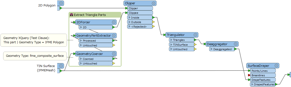
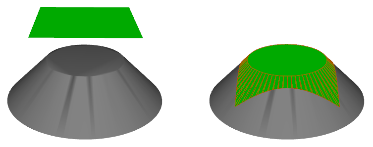
I think we must triangulate the polygons before draping them on the surface, but I don't know how to make it using FME transformers!

icon

Best answer by takashi 21 May 2016, 01:43

View original

13 replies

Userlevel 2
Badge +17

Hi @evaniko, the Triangulator transformer might help you.

Badge

Hi @takashi and thanks for the reply, but how triangulate my polygons according to the TIN and drape them after??

Userlevel 2
Badge +17

Hi @evaniko, my intention was to triangulate the polygon first and then drape the resulting triangles by the TIN surface (VERTEX Method). The result may not be ideal, but individual triangles will be planer.

If the result is not undesirable, you need another approach. For example,

  1. Extract individual triangle parts from the TIN surface.
  2. Clip the triangles by the polygon.
  3. Drape the clipped parts by the original TIN surface.

This workflow does that. Hope this helps.

[Addition] If you need to aggregate the draped features for each original polygon, check the Merge Attributes option in the Clipper and aggregate the resulting features grouping by a unique identifier attribute of the original polygon.

A demo. Left: 2D polygons and a TIN surface; Right: Draped polygons on the TIN

[Update] I found a case where non-triangle draped features will not be planar. It's better that you add some transformers to force the extracted TIN parts to 2D (2DForcer) and triangulate the clipped parts before draping (Triangulator and Deaggregator).

Badge

Yes I was wondering how can 2D polygons clip 3D triagle parts perfectly in your first solution, and I tested it and got some problems with the faces in the Sketchup format (*.skp). But now it works great with the amelioration that you added in the update!! thanks you so much for your help Takashi.

Userlevel 2
Badge +17

Yes I was wondering how can 2D polygons clip 3D triagle parts perfectly in your first solution, and I tested it and got some problems with the faces in the Sketchup format (*.skp). But now it works great with the amelioration that you added in the update!! thanks you so much for your help Takashi.

Good to hear. I read your question again and noticed you are using the TINGenerator to create the TIN surface. If the draping operation will be performed in the same workspace, you can connect the Triangles port of the TINGenerator to the 2DForcer directly and remove the GeometryCoercer and GeometryPartExtractor.

Userlevel 2
Badge +17

Yes I was wondering how can 2D polygons clip 3D triagle parts perfectly in your first solution, and I tested it and got some problems with the faces in the Sketchup format (*.skp). But now it works great with the amelioration that you added in the update!! thanks you so much for your help Takashi.

1. Maybe these additional transformers work to generate a better result.

  1. PlanarityFilter: Set "Yes" to the Expose Surface Normal parameter to expose the normal vector attributes - _surfaceNormalX, _surfaceNormalY, and _surfaceNormalZ.

  2. AttributeRounder: Round the three attributes by an appropriate decimal places, to absorb the slight computational error.

  3. Dissolver: Set the three attributes to the Group By parameter to dissolve coplanar polygons.

[Addition] Because there is unavoidable computational error, it may not be guaranteed that the resulting non-triangle polygons have planarity strictly.

0684Q00000ArM5jQAF.png

2. If the number of possible attribute values (i.e. colors) is not so many, I would create an external CSV table to define mapping between each attribute value and corresponding "fme_color" value, and merge the color value to the features with the Joiner. e.g.

Key Attribute, fme_color
1, "0,0,0"
2, "1,0,0"
3, "0,1,0"
4, "0,0,1"
5, "1,1,1"

Then, copy the "fme_color" value to "fme_fill_color" with the AttributeCopier.

The AttributeValueMapper may also be useful.

Or, if the color may be random, the FeatureColorSetter can be used simply (Color Schema: Random, Randomize Based On: Attributes).

Badge

1. Maybe these additional transformers work to generate a better result.

  1. PlanarityFilter: Set "Yes" to the Expose Surface Normal parameter to expose the normal vector attributes - _surfaceNormalX, _surfaceNormalY, and _surfaceNormalZ.

  2. AttributeRounder: Round the three attributes by an appropriate decimal places, to absorb the slight computational error.

  3. Dissolver: Set the three attributes to the Group By parameter to dissolve coplanar polygons.

[Addition] Because there is unavoidable computational error, it may not be guaranteed that the resulting non-triangle polygons have planarity strictly.

0684Q00000ArM5jQAF.png

2. If the number of possible attribute values (i.e. colors) is not so many, I would create an external CSV table to define mapping between each attribute value and corresponding "fme_color" value, and merge the color value to the features with the Joiner. e.g.

Key Attribute, fme_color
1, "0,0,0"
2, "1,0,0"
3, "0,1,0"
4, "0,0,1"
5, "1,1,1"

Then, copy the "fme_color" value to "fme_fill_color" with the AttributeCopier.

The AttributeValueMapper may also be useful.

Or, if the color may be random, the FeatureColorSetter can be used simply (Color Schema: Random, Randomize Based On: Attributes).

1. It did'nt work for me, I think the Dissolver works only for 2D geometries, it is not?! 

2. Yes using a CSV table is more practical for couloring, big thanks, but the colors of the draped polygons are'nt displayed correctly (they are mixed with the TIN color).

0684Q00000ArMzGQAV.png

Userlevel 2
Badge +17

1. It did'nt work for me, I think the Dissolver works only for 2D geometries, it is not?!

2. Yes using a CSV table is more practical for couloring, big thanks, but the colors of the draped polygons are'nt displayed correctly (they are mixed with the TIN color).

  1. Although the help doc on the Dissolver says "This transformer accepts two-dimensional polygonal features", in my observation, it also works in fact for 3D polygons except vertical wall-like shapes. See also the attachment: drape-polygon-by-tin-surface-2.fmw (FME 2016.1)
  2. I guess that you are using FME Data Inspector in 3D mode to check the result. It seems to mix colors of coplanar features, but I think the color values are set correctly. Check the values for each feature with the Feature Information pane, or view the resulting 3D polygons only.
Userlevel 2
Badge +17

1. It did'nt work for me, I think the Dissolver works only for 2D geometries, it is not?!

2. Yes using a CSV table is more practical for couloring, big thanks, but the colors of the draped polygons are'nt displayed correctly (they are mixed with the TIN color).

I noticed that the SurfaceDraper adds "_aspect" and "_slope" attribute to the draped features. These attributes can also be used to make groups of coplanar features. Update: drape-polygon-by-tin-surface-3.fmw

Badge
  1. Although the help doc on the Dissolver says "This transformer accepts two-dimensional polygonal features", in my observation, it also works in fact for 3D polygons except vertical wall-like shapes. See also the attachment: drape-polygon-by-tin-surface-2.fmw (FME 2016.1)
  2. I guess that you are using FME Data Inspector in 3D mode to check the result. It seems to mix colors of coplanar features, but I think the color values are set correctly. Check the values for each feature with the Feature Information pane, or view the resulting 3D polygons only.

1. First thanks for sharing your test workflow, then yes you are right Sir! the Dissolver works; it did not work for me before because I converted my polygons into faces with FaceReplacer, in order to be able to colour front side and back side differently (the Dissolver supports only polygons).

The problem now is that the FaceReplacer rejects many polygons in the last FME version 2016.1.1 (I don't know why??), whereas it doesn't eliminate them in the 2016.0.1 version.. .

2. No, I used Sketchup to open the results; the colors are set correctly (I know it), but the fact of faces superposition which causes the color problem (Maybe there's a solution for that?)

Userlevel 2
Badge +17

Yes I was wondering how can 2D polygons clip 3D triagle parts perfectly in your first solution, and I tested it and got some problems with the faces in the Sketchup format (*.skp). But now it works great with the amelioration that you added in the update!! thanks you so much for your help Takashi.

  1. In my test workspace, the FaceReplacer @ FME 2016.1.1 beta build 16576 was able to replace every draped 3D Polygon with Face geometry. If a feature is rejected by the transformer, it will have "fme_rejection_code" attribute, which store the rejected reason. Its value might be a hint to clarify the reason.
  2. OK. I also saw that the SkechUp mixes colors of coplanar surfaces. It seems to be the behavior common to FME Data Inspector in 3D mode. A workaround I can think of is to move the objects slightly to Z-direction (+ or -) with the Offsetter before writing, so that they will not overlap in the 3D space.

Right: The gray frustum has been slightly moved to -Z direction.

Badge
  1. In my test workspace, the FaceReplacer @ FME 2016.1.1 beta build 16576 was able to replace every draped 3D Polygon with Face geometry. If a feature is rejected by the transformer, it will have "fme_rejection_code" attribute, which store the rejected reason. Its value might be a hint to clarify the reason.
  2. OK. I also saw that the SkechUp mixes colors of coplanar surfaces. It seems to be the behavior common to FME Data Inspector in 3D mode. A workaround I can think of is to move the objects slightly to Z-direction (+ or -) with the Offsetter before writing, so that they will not overlap in the 3D space.

Right: The gray frustum has been slightly moved to -Z direction.

1. I found the source of the problem : In the FME 2016.1 version, the FaceReplacer rejects some polygons because they are still aggregated (fme_geometry = "fme_aggregate" and fme_rejection_code = "INVALID_GEOMETRY_TYPE"), whereas the situation is not the same in the 2016.0 version; So to resolve that, we have to change the Mode parameter in the Deaggregator from "Flatten One Level" to "Flatten All Levels".

As a conclusion, I think your proposed method is not always perfect for merging coplanar faces; the FaceReplacer keep rejecting my polygons because of the non-coplanarity and if we rise the precision of attributes (the number of decimal places in attributes), the FaceReplacer rejects fewer polygons but in the other hand merge less number of triagles!

For my case, I discover an alternative option : the Sketchup writer has a parameter to merge coplanar faces, but in other cases, doing the process usins transformers would be the only solution to find! so it's still more practical.

2. Yes! I thought of that solution too and I believe that it is the only :D

Reply