
I used the clipper transformer to clip my dwg, (a shapefile being the clipper). The transformation worked with no errors, but when I go to inspect the output it has lost it's crs. Have looked around and there doesn't appear to be any information our there on this, any help would be great. Thanks


Userlevel 4
 +30
+30
- Evangelist
- 1880 replies
-
25 September 2017

Hi @bjudes,
Coud you share us your Workspace , Source data and log files?
Thanks,
Danilo

 +3
+3
- Contributor
- 112 replies
-
25 September 2017
Hi @danilo_inovacao
New to this, you don't want me to share the cad and shapefiles with you do you? :)
Thanks
Userlevel 4
+30
- Evangelist
- 1880 replies
-
25 September 2017
Hi @danilo_inovacao
New to this, you don't want me to share the cad and shapefiles with you do you? :)
Thanks
Thanks the log file and Workspace.
I checked 42 features were clipped. Your Writer is shapefile?
What is the error with 42 features - Inside Clipper?
Thanks,
Danilo

Hi @bjudes
could you please run your translation with full inspection (the magnifying glass tool) and inspect features that go into Clipper and into Clippee ports of the Clipper? Based on the log, your clippers (features from Shape) have coordinate system, but I am not sure about clippees, they seem to be not coordinate system aware. As Clipper output, you get clippees clipped with clippers (what a tongue twister!) If clippees indeed have no coordinate system on them, it explains why Clipper output has no coordinate system.
+3
- Contributor
- 112 replies
-
26 September 2017
Hi @bjudes
could you please run your translation with full inspection (the magnifying glass tool) and inspect features that go into Clipper and into Clippee ports of the Clipper? Based on the log, your clippers (features from Shape) have coordinate system, but I am not sure about clippees, they seem to be not coordinate system aware. As Clipper output, you get clippees clipped with clippers (what a tongue twister!) If clippees indeed have no coordinate system on them, it explains why Clipper output has no coordinate system.
I reprojected the dwg to ensure it had the IrishTM projection. I then ran with a full inspection. When the dwg went into the and out of the clipper it was still in the IrishTM projection. However when I wrote back to cad with the writer it lost its projection.
Thanks
Hi @bjudes
could you please check if your ACAD/RealDWG Writer Coordinate System Storage parameter is set to None? You can find it in Navigator, under your Writer > Parameters > Advanced. By default, the Coordinate System Storage is set to None, however you can also set it to External PRJ, Internal ESRI WKT, or Both.
+3
- Contributor
- 112 replies
-
27 September 2017
Hi @bjudes
could you please check if your ACAD/RealDWG Writer Coordinate System Storage parameter is set to None? You can find it in Navigator, under your Writer > Parameters > Advanced. By default, the Coordinate System Storage is set to None, however you can also set it to External PRJ, Internal ESRI WKT, or Both.
Thanks @LenaAtSafe
I changed the coordinate system storage parameter to both. My dwg output now holds its projection which is great. But when I open the file in cadcorp it has again lost the projection. Not sure if this is any longer your domain, but any help is appreciated?
Thanks

 +9
+9
Hi @bjudes
could you please check if your ACAD/RealDWG Writer Coordinate System Storage parameter is set to None? You can find it in Navigator, under your Writer > Parameters > Advanced. By default, the Coordinate System Storage is set to None, however you can also set it to External PRJ, Internal ESRI WKT, or Both.
Hello @lenaatsafe, is the projection in the output based on the template used or is there a way to change to the data that is being output?

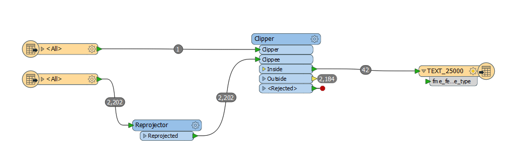
This above image is in FME Workbench before output
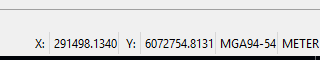
This above image is from FME Data Inspector but it seems to be adopting the projection of the DWG template?
+9
Hello @lenaatsafe, is the projection in the output based on the template used or is there a way to change to the data that is being output?
This above image is in FME Workbench before output
This above image is from FME Data Inspector but it seems to be adopting the projection of the DWG template?
Further to my above listing, the projection file created is correct but the display of the dwg projection in FME Data inspector is different (but the same). EPSG:28354 is the same as MGA94-54 but just not sure why they display differently.
Reply
Enter your username or e-mail address. We'll send you an e-mail with instructions to reset your password.