Question

Extracting slope values from contour lines to polyline network

  • 30 January 2018
  • 8 replies
  • 12 views

Badge

Hi there,


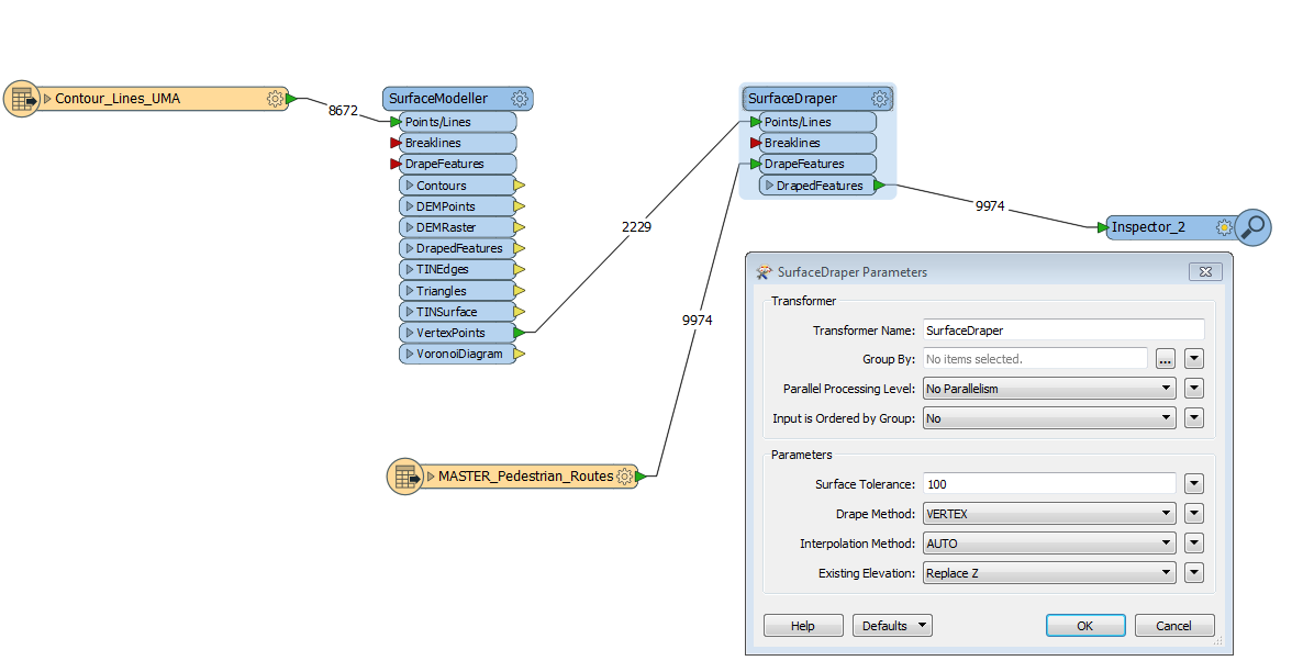
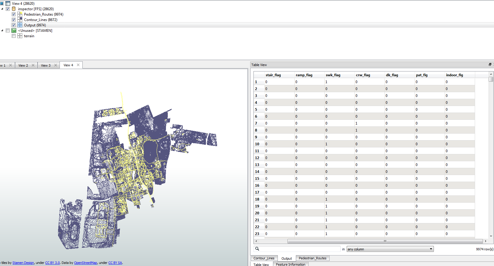
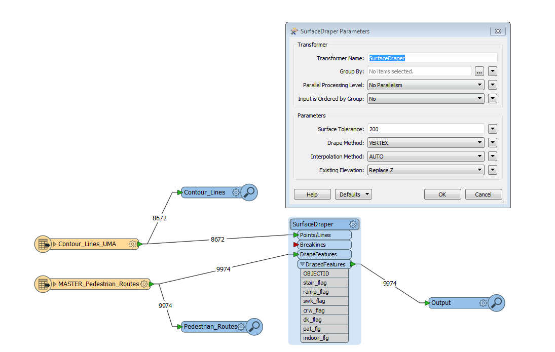
I'm working on a project where I'm trying to identify the slope of various segments along a pedestrian network based on contour lines. The ultimate goal is to create a dataset that shows changes in slope along various portions of the pedestrian network (say every 3 feet).

I'm new to working with contour lines, and I was wondering whether anyone has initial suggestions on how to approach this project in FME?

cc'ing @takashi since I've found your explanations very helpful in the past.


8 replies

Userlevel 2
Badge +16

Use the contour lines to build a 3D model (SurfaceModeler transformer).

The drape the pedestrian network over the model (SurfaceDraper transformer) to get Z values on each vertex in the network.

A slope per network segment can be calculated (using ExpressionEvaluator transformer) by dividing the length by the difference in Z value between start and end vertex.

Badge

Hi Erik,


Thanks for your quick response. I tried the method that you proposed in the workspace attached, but I'm a bit confused how you "get Z values on each vertex in the network" after using the SurfaceDraper tool. When I run the attached workspace, I don't see any Z values in the output file. Any idea what I'm not doing correctly here? Thanks in advance!

Badge

Use the contour lines to build a 3D model (SurfaceModeler transformer).

The drape the pedestrian network over the model (SurfaceDraper transformer) to get Z values on each vertex in the network.

A slope per network segment can be calculated (using ExpressionEvaluator transformer) by dividing the length by the difference in Z value between start and end vertex.

I meant to include the above answer as a comment - see above!


Userlevel 3
Badge +17

Hi Erik,


Thanks for your quick response. I tried the method that you proposed in the workspace attached, but I'm a bit confused how you "get Z values on each vertex in the network" after using the SurfaceDraper tool. When I run the attached workspace, I don't see any Z values in the output file. Any idea what I'm not doing correctly here? Thanks in advance!

If the point is located within the area of the surface, interpolated z-coordinate at the point will be added to the point. That is, the output point would be 3D. With FME Data Inspector, you can select a point and check its coordinate on the Feature Information Window.


Since the SurfaceDraper generates a surface internally based on the input 3D Points/Lines, I don't think it's essential to use the SurfaceModeller in this case.


Userlevel 3
Badge +17

Hi Erik,


Thanks for your quick response. I tried the method that you proposed in the workspace attached, but I'm a bit confused how you "get Z values on each vertex in the network" after using the SurfaceDraper tool. When I run the attached workspace, I don't see any Z values in the output file. Any idea what I'm not doing correctly here? Thanks in advance!

Oops, you are going to drape line geometries, but the method is the same as a case where the target geometries are points.


Userlevel 3
Badge +17

Hi Erik,


Thanks for your quick response. I tried the method that you proposed in the workspace attached, but I'm a bit confused how you "get Z values on each vertex in the network" after using the SurfaceDraper tool. When I run the attached workspace, I don't see any Z values in the output file. Any idea what I'm not doing correctly here? Thanks in advance!

In addition, firstly make sure that the contour lines and the pedestrian routes exist in the same area with the same coordinate system.


Badge
In addition, firstly make sure that the contour lines and the pedestrian routes exist in the same area with the same coordinate system.


Hi Takashi,


Thanks for your suggestions. I confirmed that the pedestrian routes and the contour lines are in the same coordinate system (see first screenshot). I revised the FME workflow based on your suggestions (see second screenshot), but I'm finding that there's no elevation information in the output file. Any idea what could be going on? Thanks in advance!


Userlevel 3
Badge +17

Hi Erik,


Thanks for your quick response. I tried the method that you proposed in the workspace attached, but I'm a bit confused how you "get Z values on each vertex in the network" after using the SurfaceDraper tool. When I run the attached workspace, I don't see any Z values in the output file. Any idea what I'm not doing correctly here? Thanks in advance!

To check if the resulting pedestrian routes have z-coordinate, select a route feature on the View or the Table View in FME Data Inspector and take a look at its data contents on the Feature Information window. I'd recommend you to show the Feature Information window usually (FME Data Inspector Menu: View > Windows > Feature Information).


Also check if 200 is reasonable as the value of the Surface Tolerance parameter in the SurfaceDraper. See the description on the parameter in the SurfaceDraper help to learn more..


Reply