Solved

The FME is upgraded to Build 22311: How to align points converted from texts as per their (texts) alignment in AutoCAD table?

  • April 1, 2022
  • 6 replies
  • 50 views

jamal
Forum|alt.badge.img+5

The FME is upgraded to Build 22311: How to align points converted from texts  as per their (texts) alignment in AutoCAD table?


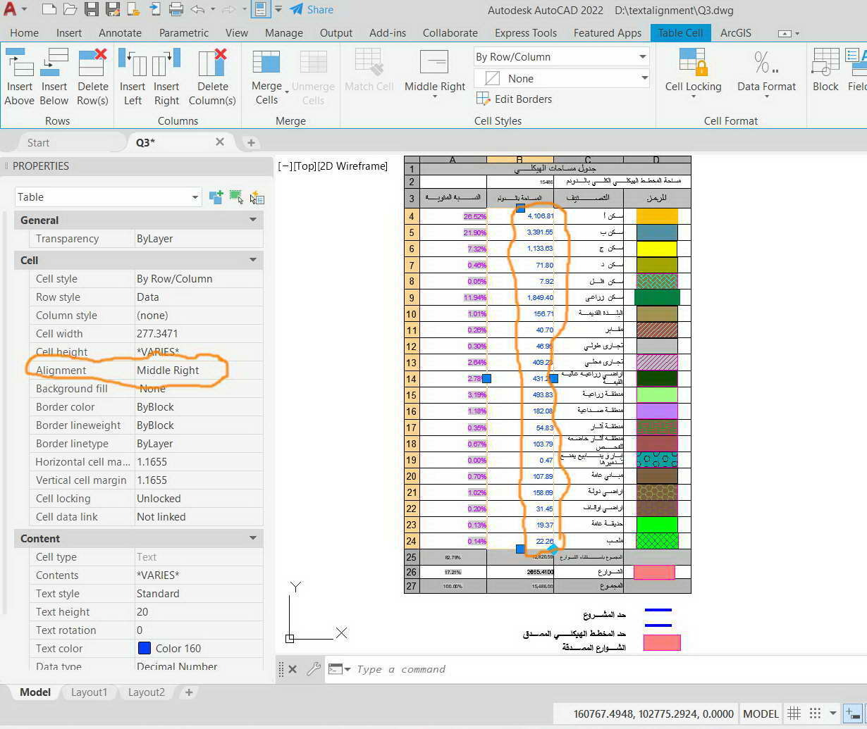
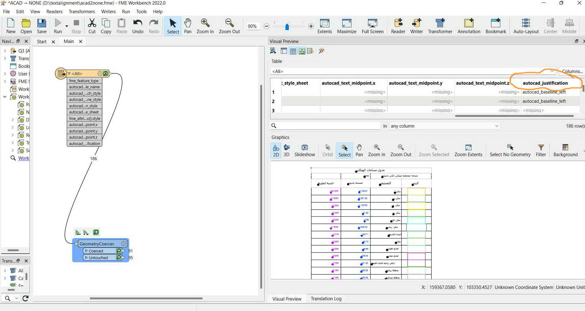
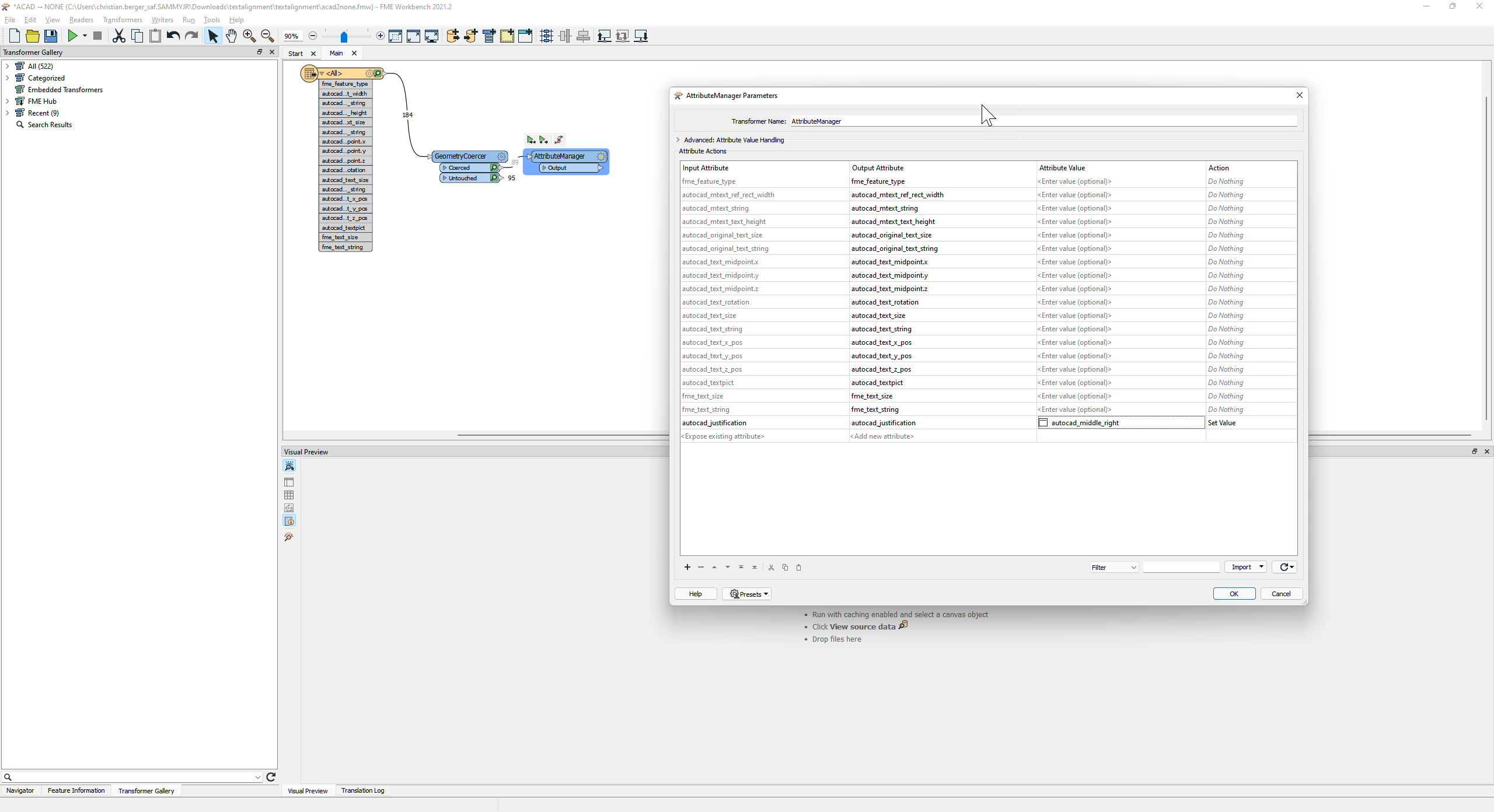
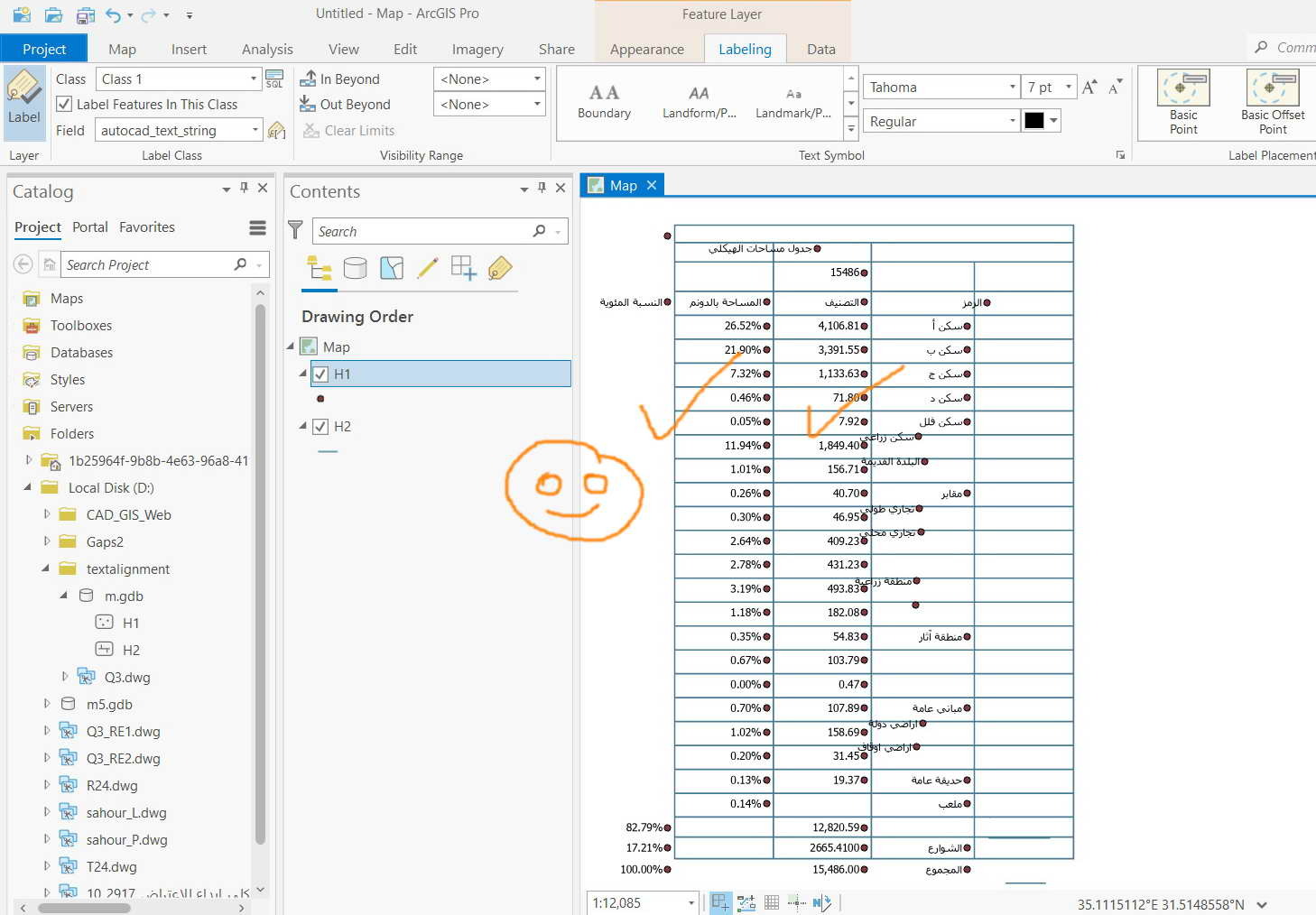
In the screenshot below, texts contained in an AutoCAD table are “middle right” aligned. How to keep this alignment as they are converted to points so that they are kept vertically aligned?


The dwg file is attached


Clip_349 


Clip_350 


Best answer by chrisatsafe

It’s set but with no effect of the points. They are kept in the same place


Clip_370

Ah you are looking for aligning the point rather than the justification (or both). You can try using the TopologyBuilder, AnchoredSnapper, and Offsetter to control where the insertion point.


Here is an example, you'll likely need to play with the values and filtering, etc.

image

This post is closed to further activity.
It may be an old question, an answered question, an implemented idea, or a notification-only post.
Please check post dates before relying on any information in a question or answer.
For follow-up or related questions, please post a new question or idea.
If there is a genuine update to be made, please contact us and request that the post is reopened.

6 replies

chrisatsafe
Contributor
Forum|alt.badge.img+2
  • Contributor
  • 606 replies
  • April 1, 2022

Hi @jamal​ ,

You should be able to preserve this by setting the autocad_justification format attribute to autocad_middle_right as outlined in this article: https://community.safe.com/s/article/text-justification

Hope that helps!


jamal
Forum|alt.badge.img+5
  • Author
  • 342 replies
  • April 1, 2022

I couldn’t figure out how to set “autocad_justification” to be “autocad_middle_right”


Clip_369


chrisatsafe
Contributor
Forum|alt.badge.img+2
  • Contributor
  • 606 replies
  • April 1, 2022

I couldn’t figure out how to set “autocad_justification” to be “autocad_middle_right”


Clip_369

Connect an AttributeManager to the GeometryCoercer's coerced output port, then in the AttributeManager type autocad_justification into a new row in the Input Attribute column and set the attribute value accordingly.

image


jamal
Forum|alt.badge.img+5
  • Author
  • 342 replies
  • April 1, 2022

It’s set but with no effect of the points. They are kept in the same place


Clip_370


chrisatsafe
Contributor
Forum|alt.badge.img+2
  • Contributor
  • 606 replies
  • Best Answer
  • April 1, 2022

It’s set but with no effect of the points. They are kept in the same place


Clip_370

Ah you are looking for aligning the point rather than the justification (or both). You can try using the TopologyBuilder, AnchoredSnapper, and Offsetter to control where the insertion point.


Here is an example, you'll likely need to play with the values and filtering, etc.

image


jamal
Forum|alt.badge.img+5
  • Author
  • 342 replies
  • April 2, 2022

Thank you very much for the help. It works fine. Just I need to work on better aligning the Arabic fonts


Clip_376