Question

How do you capture the full extend of a vector when rasterizing?

  • March 9, 2026
  • 2 replies
  • 105 views

thespatialist
Participant
Forum|alt.badge.img+1

How can one rasterize a vector where all cells touched by a polygon/vector get drawn during rasterization?

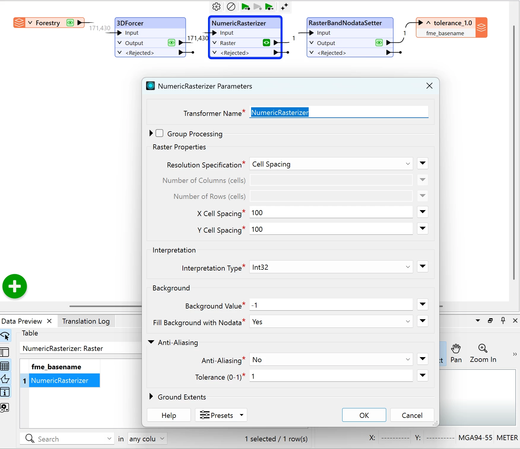
I have tried the NumericRasterizer, but I believe there’s an issue with tolerance values greater than 0.5 not being respected when using the NumericRasterizer transformer.

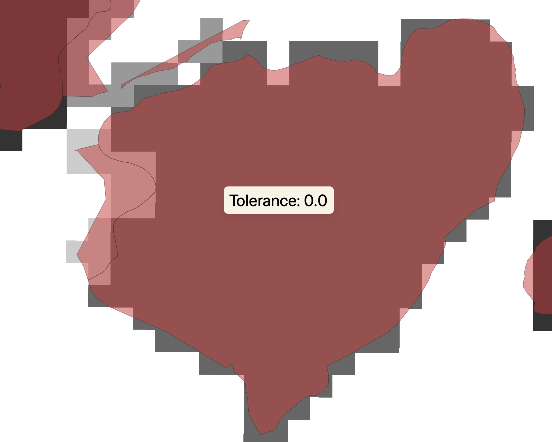
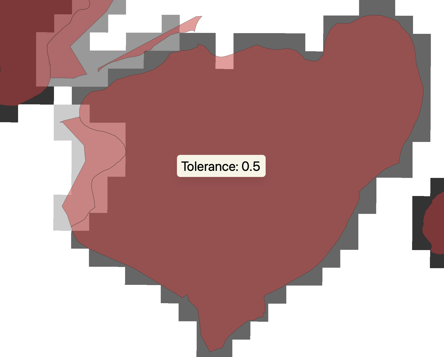
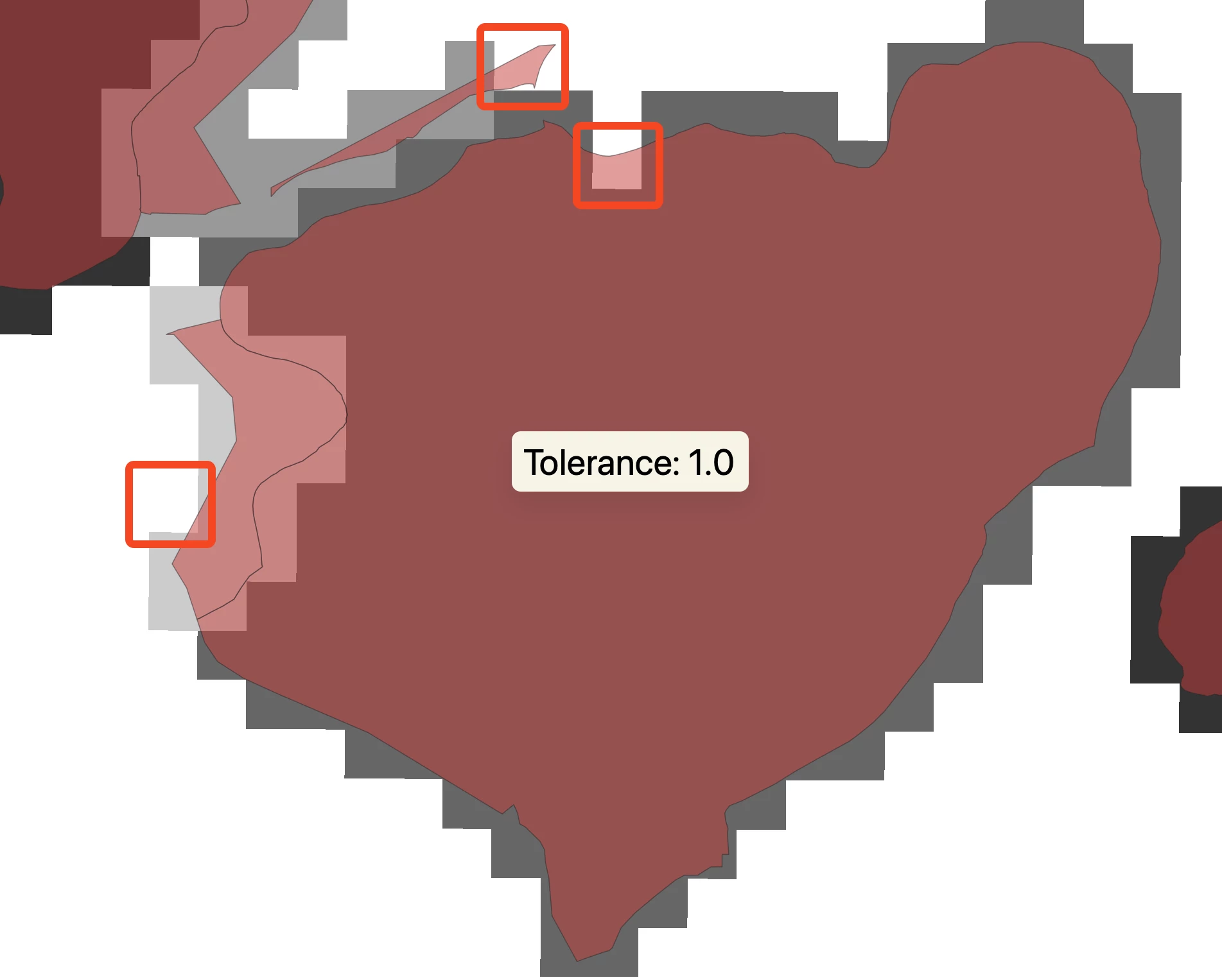
With tolerances like 0 and 0.5, I can see a difference in output. However, a tolerance value of 1.0 has no change in the output (see below).

Output from NumericRasterizer with tolerance set to 0.0, with the input vector overlayed


Output from NumericRasterizer with tolerance set to 0.5, with the input vector overlayed


Output from NumericRasterizer with tolerance set to 1.0, with the input vector overlayed


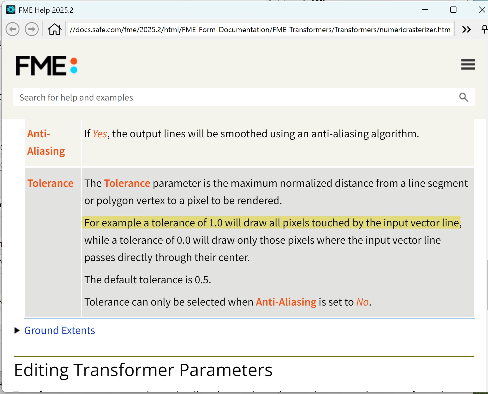
Going by the documentation, it explicitly states that a tolerance of 1.0 will draw all pixels touched by the input vector line, which can been seen above as not being seen in the output.

Work flow and NumericRasterizer parameters


Documentation of the tolerance parameter from the corresponding version of FME Form


I have tested values such as 0.7 0.8, 0.9, and 0.999 with no luck.


Does anyone know if this is intentional or a bug? And if not, how might one achieve a perfect rasterization as described when the value is 1.0?


This was tested in FME Form/Workbench 2025.2.3. 

2 replies

max_h
Enthusiast
Forum|alt.badge.img+27
  • Enthusiast
  • March 10, 2026

It is always trying to approximate from the inside as far as I know.
So I guess a way (probably not the most elegant one) would be:

  • buffer your polygon
  • rasterize it
  • intersect/clip it with your original polygon an set all non-overlapping(outside) cells to no data

jamatsafe
Safer
Forum|alt.badge.img+19
  • Safer
  • March 16, 2026

Hi ​@thespatialist, I agree, what you're seeing does not match the documented behavior of the Tolerance parameter within the NumericRasterizer. We already have this filed under FMEENGINE-83896 and we’ll share an update once the issue has been resolved!

In the meantime, the temporary workaround suggested by ​@max_h is a great option to try.

Buffer polygon > NumericRasterizer > Clipper (set ‘Determine Cell Location By’ to Bounds) to output more consistent results.

The vector input for the Clipper may also need a small buffer. The amount depends on raster cell size and grid alignment and can prevent edge pixels from being incorrectly excluded along the polygon boundary.