Question

Drone image footprint calculation

  • 10 October 2022
  • 9 replies
  • 161 views

Hi,


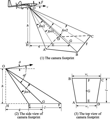
We would like to be able to calculate the real world footprint of drone images to result as a trapezoid polygon. This should be possible with only the exifdata that we get from the custom transformer "exifReader" as far as I can tell.


I found a python version here, but it requires additional installation of vector3d from the python script. Anyone got a solution to calculate drone image footprints?

https://gist.github.com/luipir/dc33864b53cf6634f9cdd2bce712d3d9


The custom transformer FootprintCreator promises something similar but requires a CSV-file from the camera. Anyone got a suggestion/solution? It would be a neat transformer that I think a lot of people would benefit from. We have a couple of different DJI drones.


9 replies

Badge +10

Hi @leif​  have you tried the boundingboxreplacer after reading in the imagery? https://www.safe.com/transformers/bounding-box-replacer/

Hi @leif​  have you tried the boundingboxreplacer after reading in the imagery? https://www.safe.com/transformers/bounding-box-replacer/

Hi @carmijo​ 

The boundingboxreplacer might be a solution if we are only talking about images with the camera pointing straight towards the ground. I am after something that generates the real world footprint no matter which camera pitch is being used. Even if the photo is at the horizon, the polygon should extend to reflect that.


What I am after:

drone_image

Badge +10

Hi @carmijo​ 

The boundingboxreplacer might be a solution if we are only talking about images with the camera pointing straight towards the ground. I am after something that generates the real world footprint no matter which camera pitch is being used. Even if the photo is at the horizon, the polygon should extend to reflect that.


What I am after:

drone_image

I see. sorry i can't help further. good luck!

Userlevel 2
Badge +17

Hi @leif​,

I think this is doable using the exif parameters and the new surface clipping capability in FME. You can use the sensor size and focal length parameters to create a pyramid, then align it to the camera path and scale by (height ASL * 2 )/ focal length. Use the pyramid to clip a DEM surface (if you have it) or a flat surface at the height AGL to get the footprint.

If you would like to share an FFS of the output of the ExifReader, I will see what we can do with the information it provides.

Hi @daveatsafe​,

Thank you so much! Any help with this would be appreciated. I have uploaded the FFS output of the ExifReader when it is reading one image. This is the test image in question:Drone image

Userlevel 2
Badge +17

Hi @leif​,

I was able to use the FOV exif value with the image height and width to calculate the perspective pyramid. I gave it a very long distance to ensure a good intersection with the ground plane.

I made a few assumptions:

  • Zero degrees flight yaw is due north
  • At zero degrees gimbal pitch the camera points straight down
  • Camera elevation above ground is relative elevation

Please try the attached workspace and check the results to make sure these assumptions are valid

If you have a ground elevation model, you can create a surface from it and clip that instead of the ground plane to get a more accurate footprint. If you do this, set the camera height in the Offsetter transformer to Absolute height instead of Relative height.

Nice going! Looks promising, but we are experiencing problems with the rotation/yaw. From what I can tell, your assumption that zero degrees flight yaw is due north is correct. The image in question should point towards the big white van on the left. The workbench you provided uses @Value(FlightYawDegree)+@Value(GimbalYawDegree) to rotate along the Z Axis, and that would translate into -140.5 degrees. A more realistic number on this image would be -190.

screenshot1
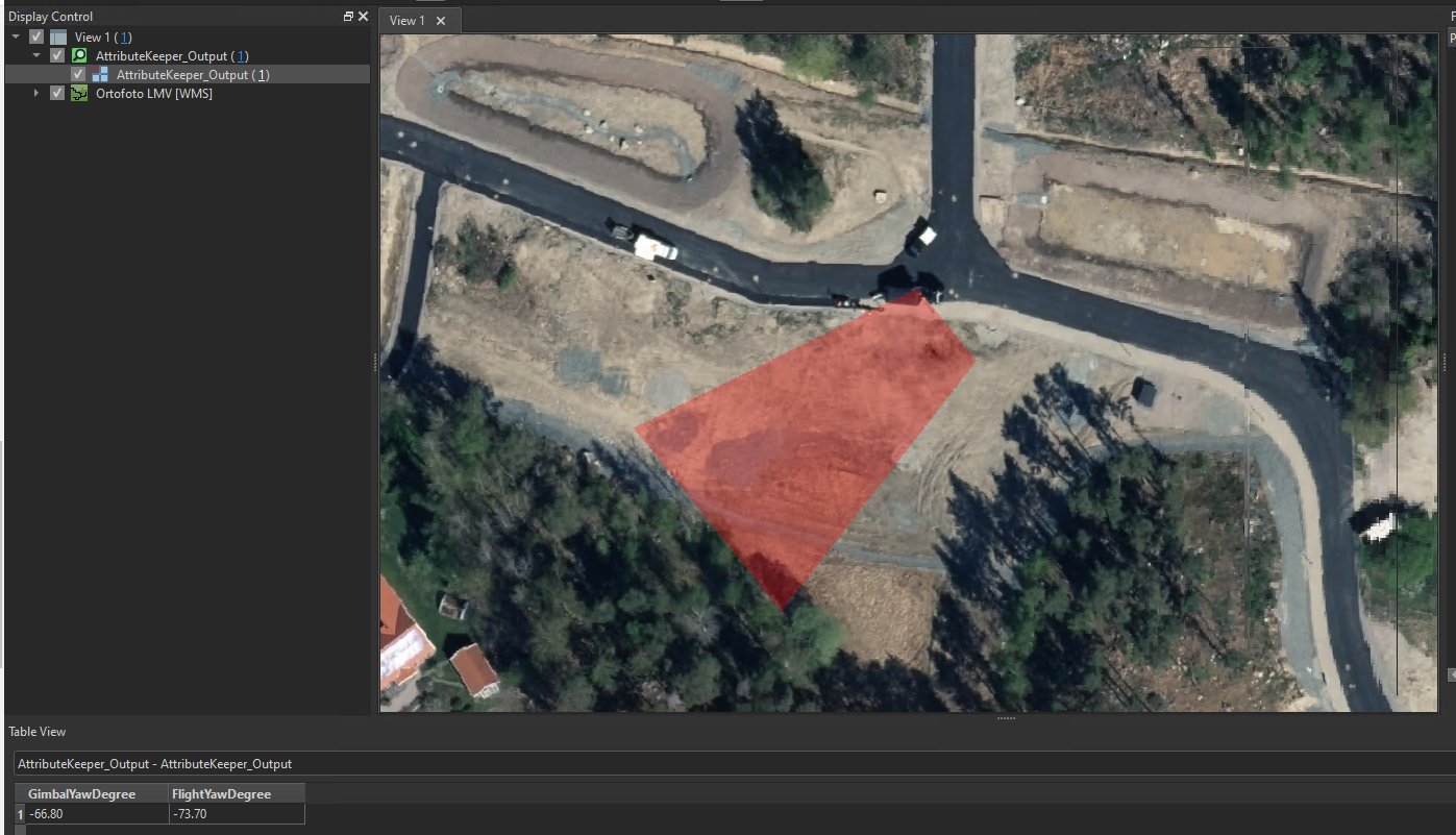
Any ideas? Could the problem lie with our drone readings or is there something else? Have you had the chance to test the workflow on any drone images you have?


Another small problem is that only one pyramid is being built, no matter how many images are being used as input. 16 images resulted in 1 solid generated and 75 unused objects from the SolidBuilder. This is a small detail though.

Userlevel 2
Badge +17

Hi @leif​,

Thank you for the feedback. It looks like the Gimbal directions already include the Flight directions, so there is no need to combine them. I have adjusted the rotation values and yaw direction to adjust for this.

While researching this, I found that the yaw angle is magnetic, not true, so I added call to NOAA's magnetic declination API to get the adjustment to true north and apply it.

Finally, I set Grouping on several transformers so the workspace will properly handle multiple inputs.

Please try this version and let me know if the results are correct.

Badge +1

How to do i modify the above workbench to add a dem?

Reply