Solved

Light source vector definition within the SurfaceFootprointReplacer transformer

  • 4 August 2022
  • 1 reply
  • 4 views

I've been trying to work out how the light source definition is actually used within the SurfaceFootprointReplacer (with shadow mode set to perpendicular) transformer without luck.


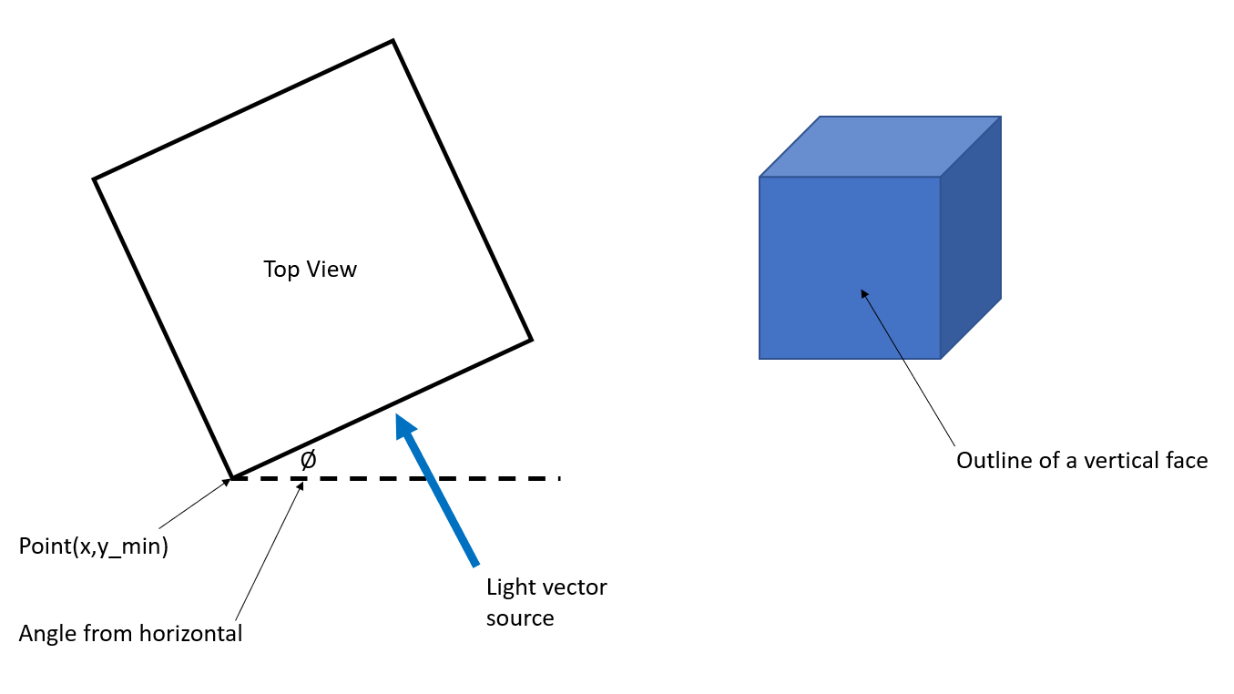
My end goal would be to extract an estimated surface of a 3D shape for a hydraulic radius calculation. If I know the shape's rotation from the horizontal axis, how does this get defined by the vector parameters?

LightSourceDefDefining a point along the face didn't appear to be the right answer, nor was offsetting a point...


A simplified workflow showing a cube rotated 45° is attached to illustrate the issue.

icon

Best answer by nampreetatsafe 16 August 2022, 02:38

View original

1 reply

Userlevel 1
Badge +10

Posting an update here since a support case was created for this question. @geo91​ eventually resolved this by rotating to the X axis, offsetting to the origin (added 1000 to Y), putting the vector at the centroid of the shape and then reversing the process to put it back into its correct location.


Our @deanatsafe​ provided the following information for context:


I'm not sure the SurfaceFootPrintReplacer is doing what you expect in this case. I agree that the docs on this are somewhat limited and could use an update. There is a current bug report in our dev system to this effect.


To better explain how it works, you can specify the "tip" of the vector by giving an XYZ, and the "tail" of the vector is assumed to be 0,0,0. That gets the direction that light would be travelling, and then we assume that the light source starts at infinitely far away towards the "tail" direction - that is towards 0,0,0. For this functionality it is likely best to use 'Perpendicular Shadow' as you are already using in your workspace.


In your case however, the cube was created with an origin at 100,100 so I'm not sure the light source origin of 0,0,0 will work as you expect. Given that the light source is pointing at 0,0,0, I expect you would likely need to translate your 3d feature to centre on 0,0,0 before generating the shadow.


I'm no expert in hydraulics, but based on what I have read for a hydraulic radius calculation, you would likely want to set the light up to be normal to the plane representing the cross section you want to produce the hydraulic radius for. So the light source would be along the path vector of the pipe or channel to generate a cross section perpendicular to the flow vector. Ideally you would need to translate the pipe so that the centre is at 0,0,0 for each segment before making each shadow.


Attached is a much simpler test case for the SurfaceFootPrintReplacer.

Reply