Question

IFC to CityGML - Representation of WallSurface

  • 25 March 2022
  • 3 replies
  • 6 views

Hi there, I'm converting IFC to CityGML following the tutorial FME shared here: https://community.safe.com/s/article/bim-to-gis-intermediate-ifc-lod-300-to-lod-4-cityg.


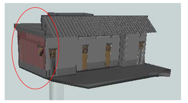
It is noticed that the representation of WallSurface is quite strange (red lines on the surface). May I know the reason and if there are any solution to make the wall surface shown as smooth surface like others? Thanks in advance!

WallSurface in red lines


3 replies

Userlevel 4
Badge +26

To me this looks like an artifact of two surfaces over the top of each other. The red usually indicates the back side of a surface. So I think what you see is tow surfaces in the same spot, one pointing outwards and one pointing inwards

To me this looks like an artifact of two surfaces over the top of each other. The red usually indicates the back side of a surface. So I think what you see is tow surfaces in the same spot, one pointing outwards and one pointing inwards

Thanks for your reply! Are there any methods that I could define the wall surface as external or internal during the conversion from IFC to CityGML?

Userlevel 4
Badge +26

Thanks for your reply! Are there any methods that I could define the wall surface as external or internal during the conversion from IFC to CityGML?

In this case you could try and use a SurfaceDissolver. You might have luck with this method. This should at least merge the two surfaces into one. The problem then becomes if the output is correctly oriented or not. This can only really be solved properly is the surfaces make up a composite surface or a solid. The GeometryValidator can detect incorrectly oriented surfaces but only is they are part of a CompositeSurface or Solid.


Reply