


They have more in common with the Min and Max Extents in the Feature Information window than down below where the geometry coordinates are. Should I expect the indices to align with the existing coordinates? Do aggregates change how the CoordinateExtactor works? It is really mystifying. Any insight is appreciated.
Best answer by virtualcitymatt
View original


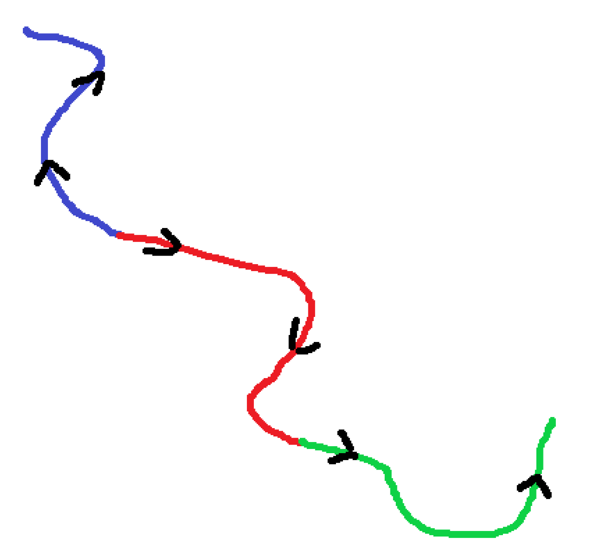 These lines are all topologically valid (each line that touches shares the same vertex). Notice how the blue line is drawn in a different direction to the red and the green.
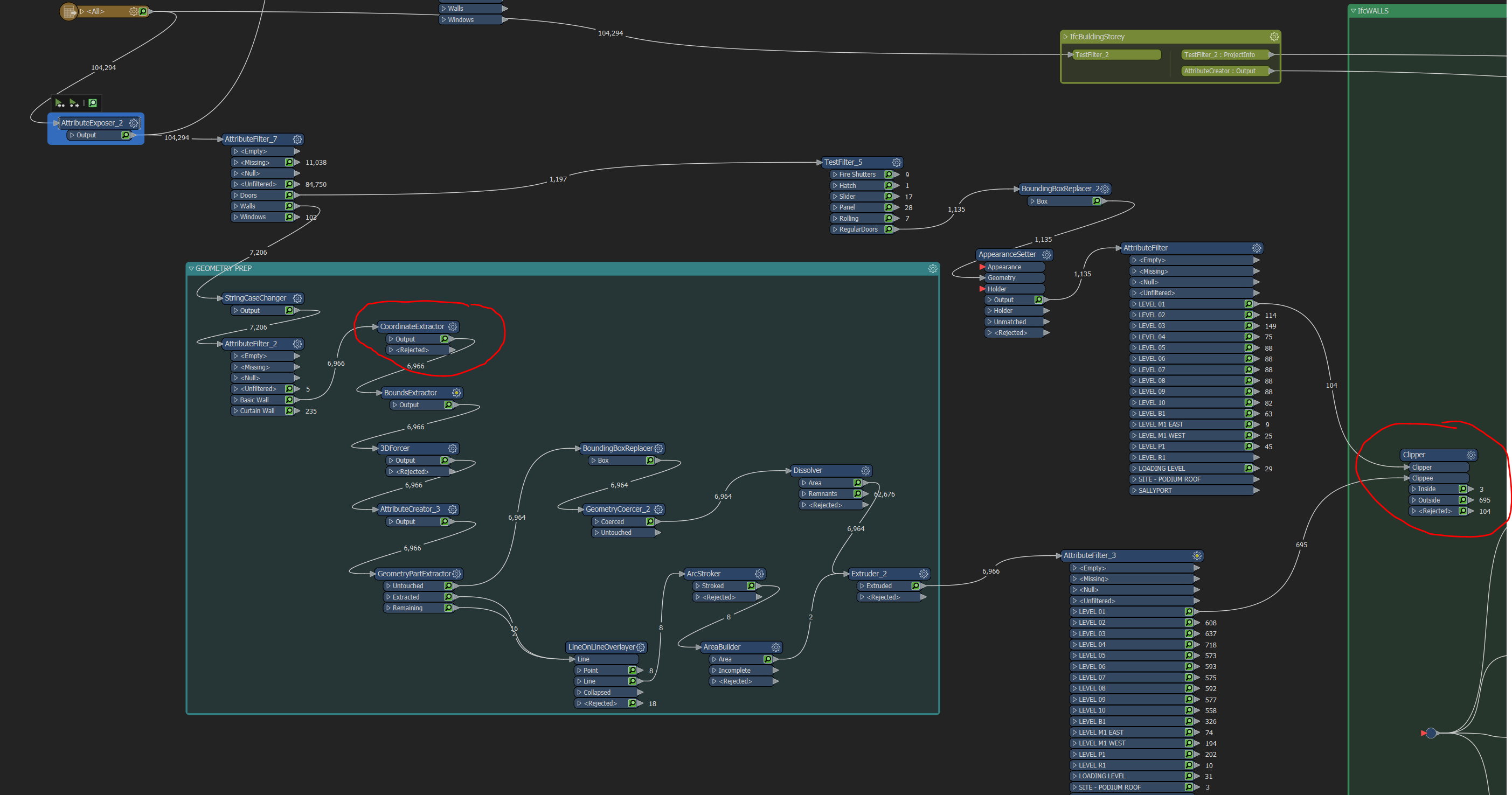 The red circles are where I got the Feature info and the output for visual preview, respectively.
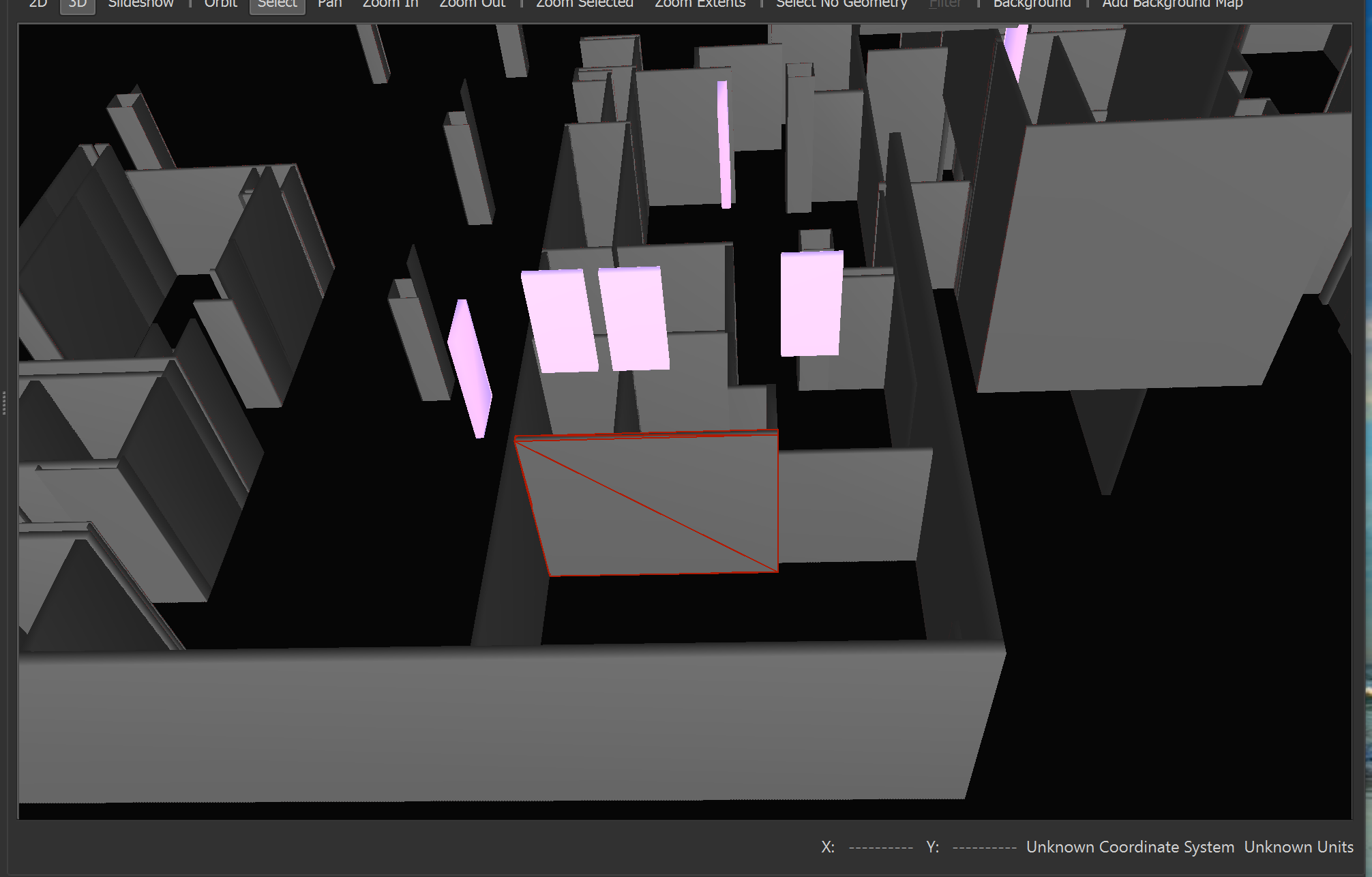 The selected wall is the feature in the attachments, only flattened and extruded using the bounds as a base. _zmax -_zmin = Extrusion distance.
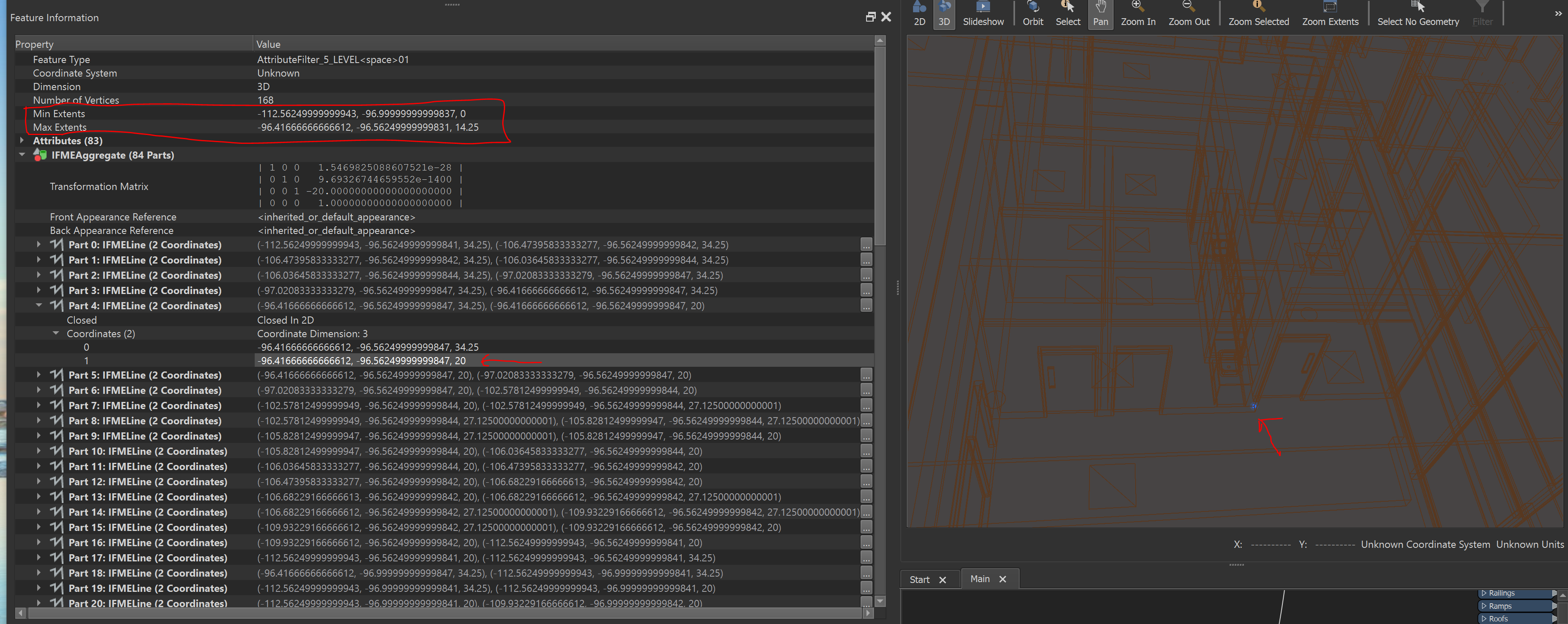


 I think the issue here is that the Geometry you see in the Feature Information window is not the real geometry - the extracted coordinate and bounds reflect the real geometry.