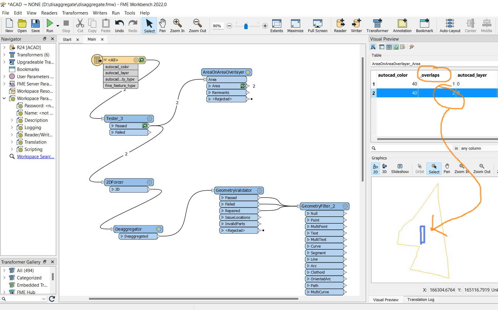

FME Desktop 2022: Disaggregating two polygons gets them unexpectedly three,
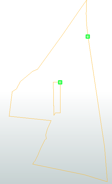
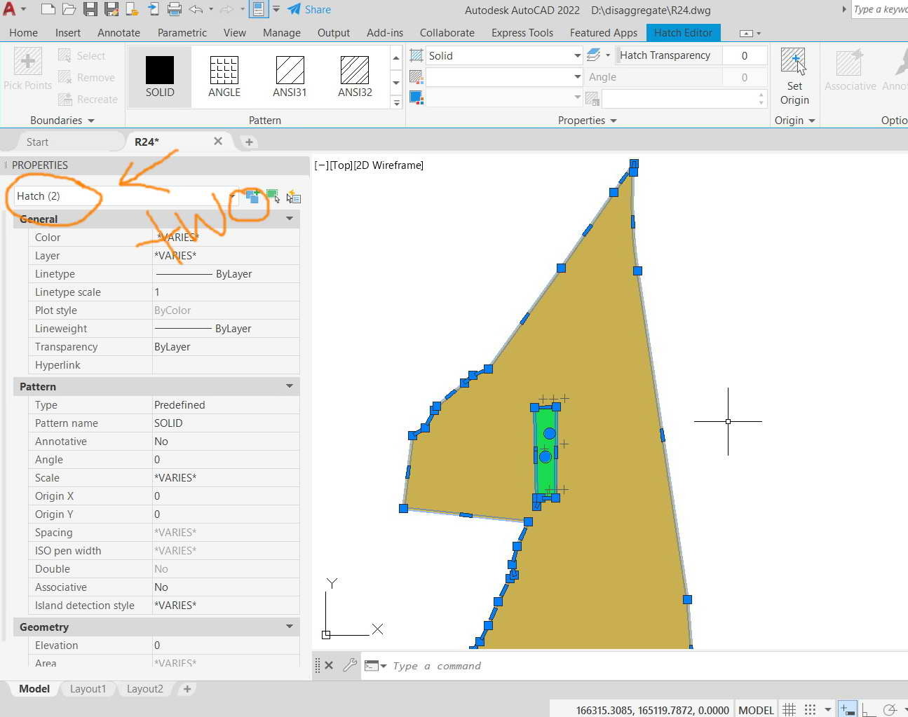
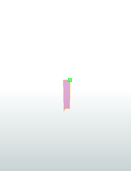
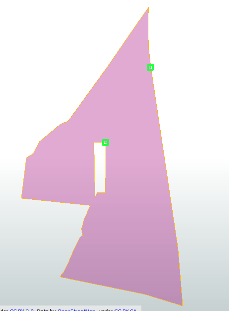
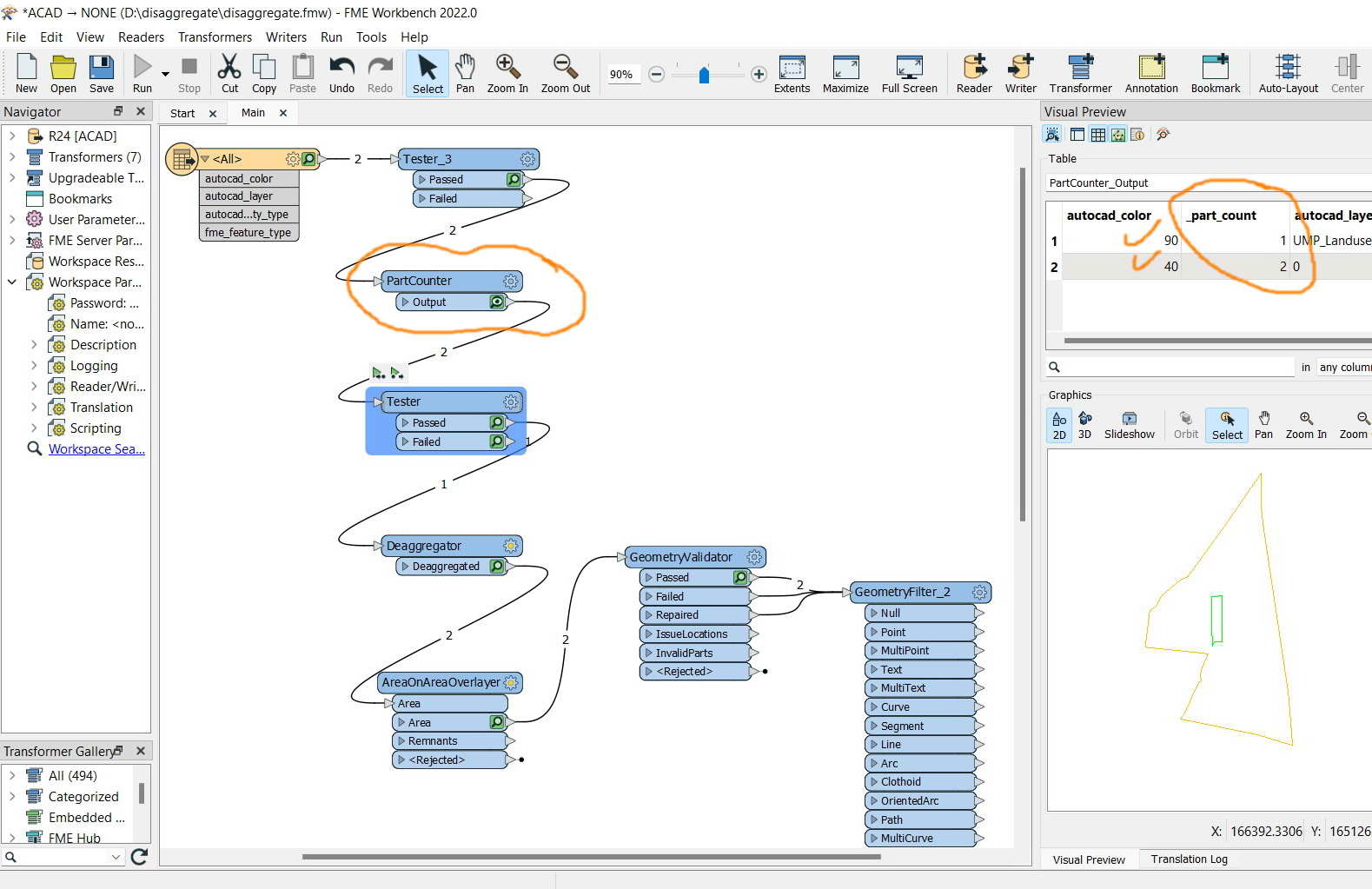
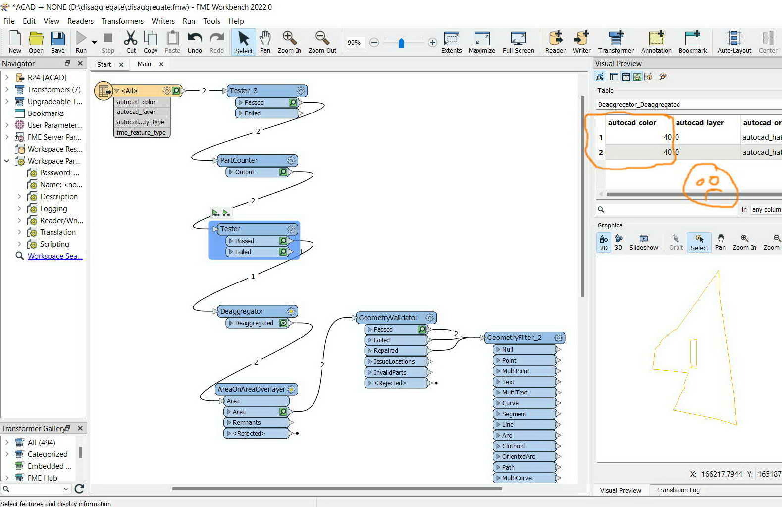
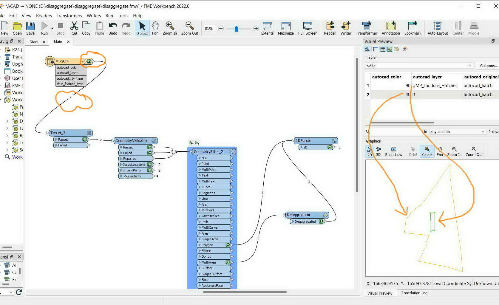
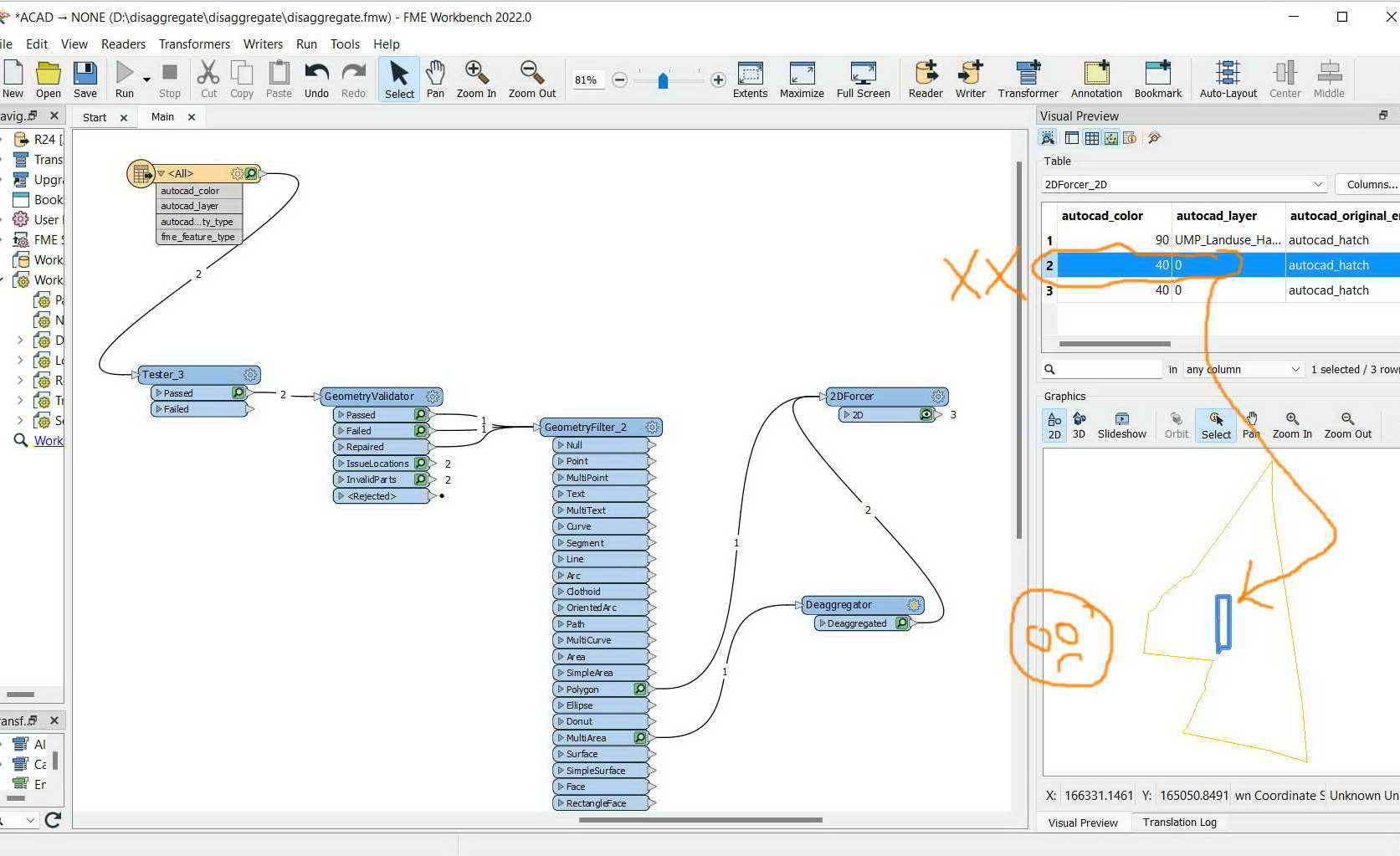
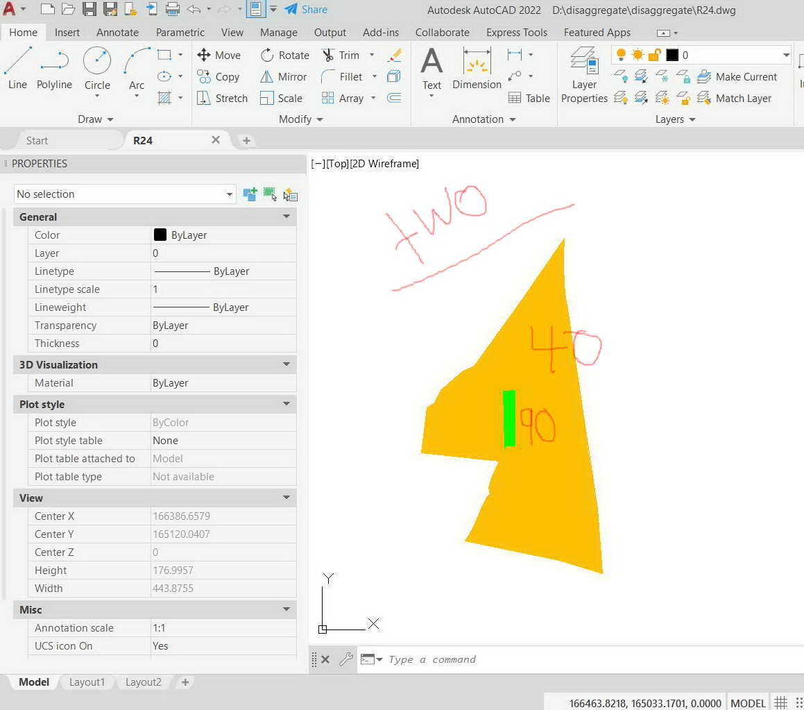
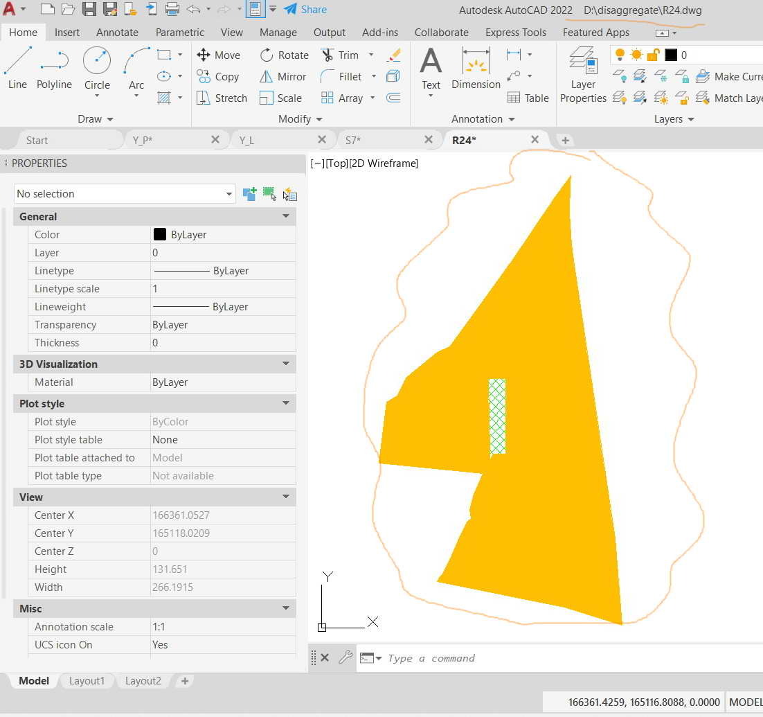
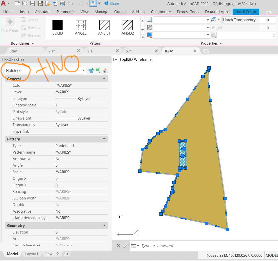
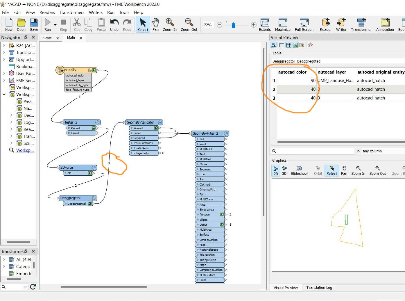
In the screenshot below, I got two polygons. However, as they are disaggregated I got three while they should remain two in this case as they are physically two from their native source with no reason to become three.
What could be the issue here?
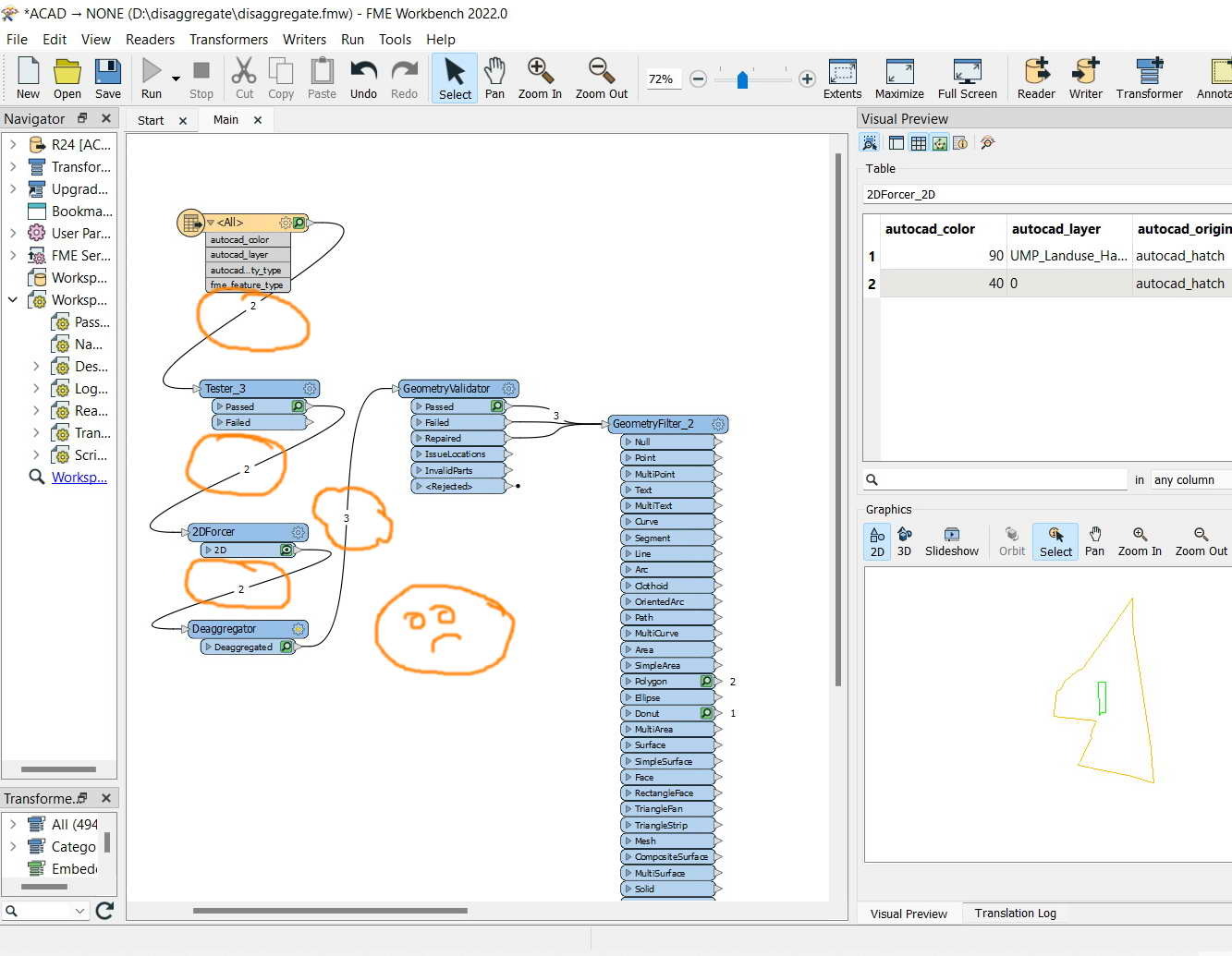
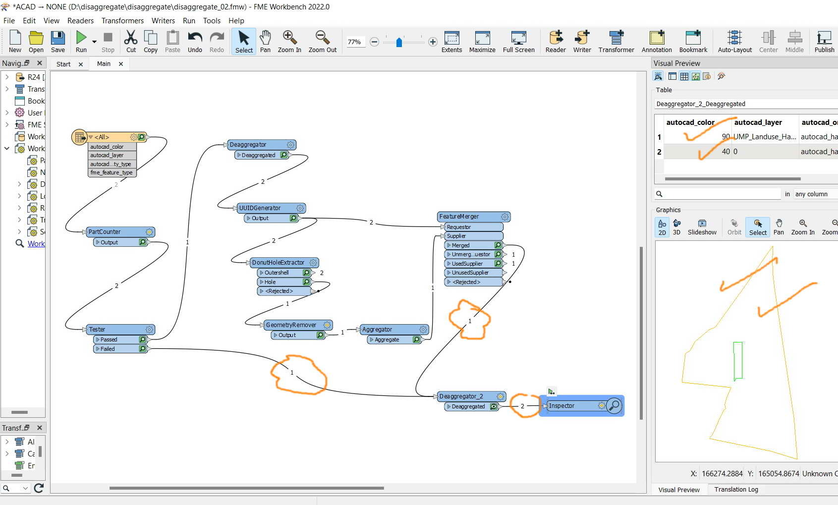
The data and workbench are attached
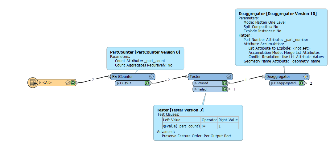
Best answer by hkingsbury
View original


 G2:
G2: