Question

Best way to overcome vertical faces in a triangulation surface

  • 19 February 2022
  • 6 replies
  • 27 views

Badge +1

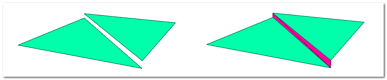
I have an array of polygons representing a surface triangulation.

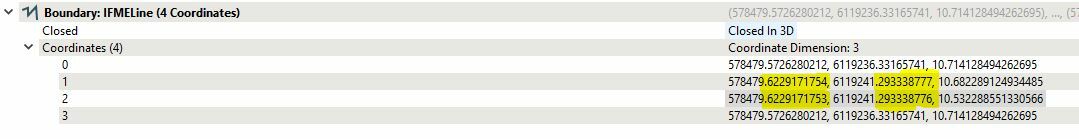
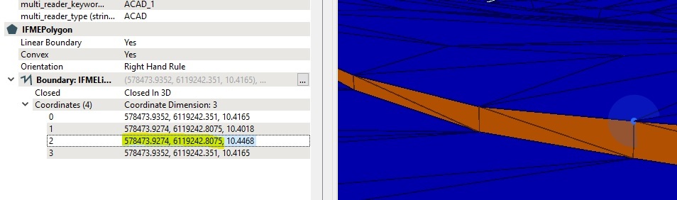
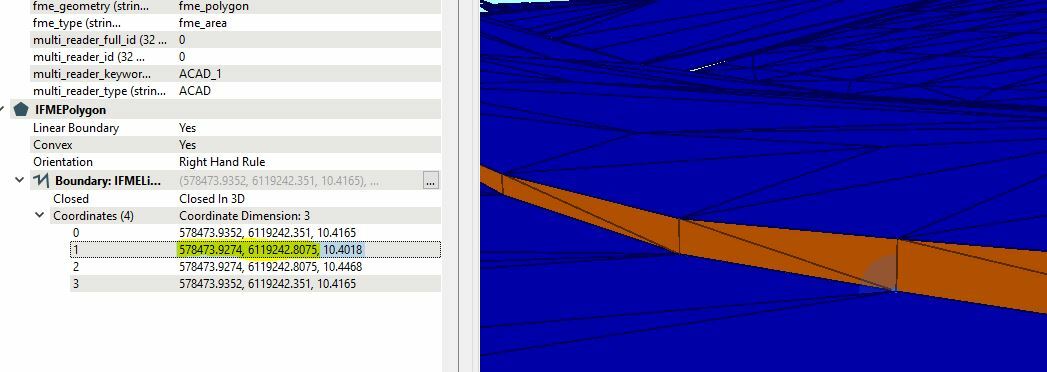
Because of the source of the data, some faces are vertical which aren't supported in the TIN I'm trying to create.

Any ideas on what would be the best way to overcome this? I'm sure its a common issue, be interested to see how others handle it.

Maybe convert to lines, filter overlapping lines with different Z values and offset both a small amount?


6 replies

Userlevel 2
Badge +17

Hi @kelvin.jenkins​ , it's an interesting challenge. I don't know if it's the best way, but the attached workspace is a theoretically possible way.vertical-faces

Badge +1

Hi @kelvin.jenkins​ , it's an interesting challenge. I don't know if it's the best way, but the attached workspace is a theoretically possible way.vertical-faces

Hi @Takashi Iijima​ , Thanks for sending through your example.

I've run my data through this and it does create the faces, but looking at the coordinates the result is still essentially a vertical face, be it 0.0000000001 offset. Would there be a way to tweak this workflow to increase the offset between top and bottom? As the destination software will round to 4 decimals.

I've uploaded a copy of the data for reference

Vertical Face Result'

Userlevel 2
Badge +17

Hi @Takashi Iijima​ , Thanks for sending through your example.

I've run my data through this and it does create the faces, but looking at the coordinates the result is still essentially a vertical face, be it 0.0000000001 offset. Would there be a way to tweak this workflow to increase the offset between top and bottom? As the destination software will round to 4 decimals.

I've uploaded a copy of the data for reference

Vertical Face Result'

I upgraded the workspace example. See the attachment.

Badge +1

Hi @Takashi Iijima​ , Thanks for sending through your example.

I've run my data through this and it does create the faces, but looking at the coordinates the result is still essentially a vertical face, be it 0.0000000001 offset. Would there be a way to tweak this workflow to increase the offset between top and bottom? As the destination software will round to 4 decimals.

I've uploaded a copy of the data for reference

Vertical Face Result'

thanks takashi,

I've tested this one, but the points are still vertical faces, with each point still sharing the same horizontal position.

I did like your idea of using extrusions and surface intersections to find points, this might be the way forwardVertex 2Vertex 1

Userlevel 2
Badge +17

Hi @Takashi Iijima​ , Thanks for sending through your example.

I've run my data through this and it does create the faces, but looking at the coordinates the result is still essentially a vertical face, be it 0.0000000001 offset. Would there be a way to tweak this workflow to increase the offset between top and bottom? As the destination software will round to 4 decimals.

I've uploaded a copy of the data for reference

Vertical Face Result'

Do you mean that the resulting vertical faces are required to be slightly tilted, like this screenshot?vertical-faces-desired-result

Badge +1

Hi @Takashi Iijima​ , Thanks for sending through your example.

I've run my data through this and it does create the faces, but looking at the coordinates the result is still essentially a vertical face, be it 0.0000000001 offset. Would there be a way to tweak this workflow to increase the offset between top and bottom? As the destination software will round to 4 decimals.

I've uploaded a copy of the data for reference

Vertical Face Result'

Yes, that right, it needs to be slightly offset like that. It's a requirement for a civil 3d or 12d surface Tin to not have any vertical polygons or overhanging polygons (like an overhanging cliff)

Reply