Question

Changelog of MapnikRasterizer - difference between FME version for the filling of a marker?

  • 11 February 2022
  • 7 replies
  • 4 views

Badge

Hello everyone, 


I have an issue with an automatic process generating PDFs since an upgrade of FME server from FME 2017 to FME 2021.


The process is quite complex but basically it creates network maps on demand. My issue is that, since the upgrade, the symbols rasterized on the maps are not rendered as usual.


The symbols are imported from SVG files generated from an AutoCad dwg (because the network information is from an Autocad/Oracle DB). It uses MapnikRasterizer to produce a raster version of all the information, including the symbols as markers.


I have identified the source of the difference in the rendering, it is how MapnikRasterizer handle the SVG. But I don't think it is directly related to the developement of MapnikRasterizer but how FME is integrating it and how FME handle the SVG. The SVG are made from Autocad blocks and most of them have an outline/contour of a slightly different color. So even a plain round symbol is constituted of two shapes.


My issue is that FME 2017 could fill the entire marker with the given color while FME 2021 cannot. And I say FME instead of MapnikRasterizer because it is unrelated to the version of the transformer (upgrading or keeping the old version doesn't change anything).


I have the original workbench made in FME 2017 (build 17725), which still work both in FME desktop and in FME server with the same build. If I run it with the last version of FME desktop/server it doesn't work (I got the rendering issue), even without performing any upgrade of the transformers. Upgrading all the transformers doesn't solve the process. I also tried to run it with other versions of FME desktop, the original workbench doesn't work in FME 2020.1.x but works perfectly fine in FME 2019.2.x. So in my opinion, it seems related to the version of FME and not the transformer.

I cannot upload the entire workbench with the issue due to its complexity but I have built some simpler workbenches reproducing it. Here in the zip you will find two workbenches, one made in FME desktop 2017 (MapnikRasterizer version 2) and another one made in FME desktop 2021 (MapnikRasterizer version 4). There are also the SVG files in a folder.


Those are quickly made workbenches, some symbols are quite complex and larger than others and I have simply made something to plot them all. It is not the real colors and sizes in use for the pdf.


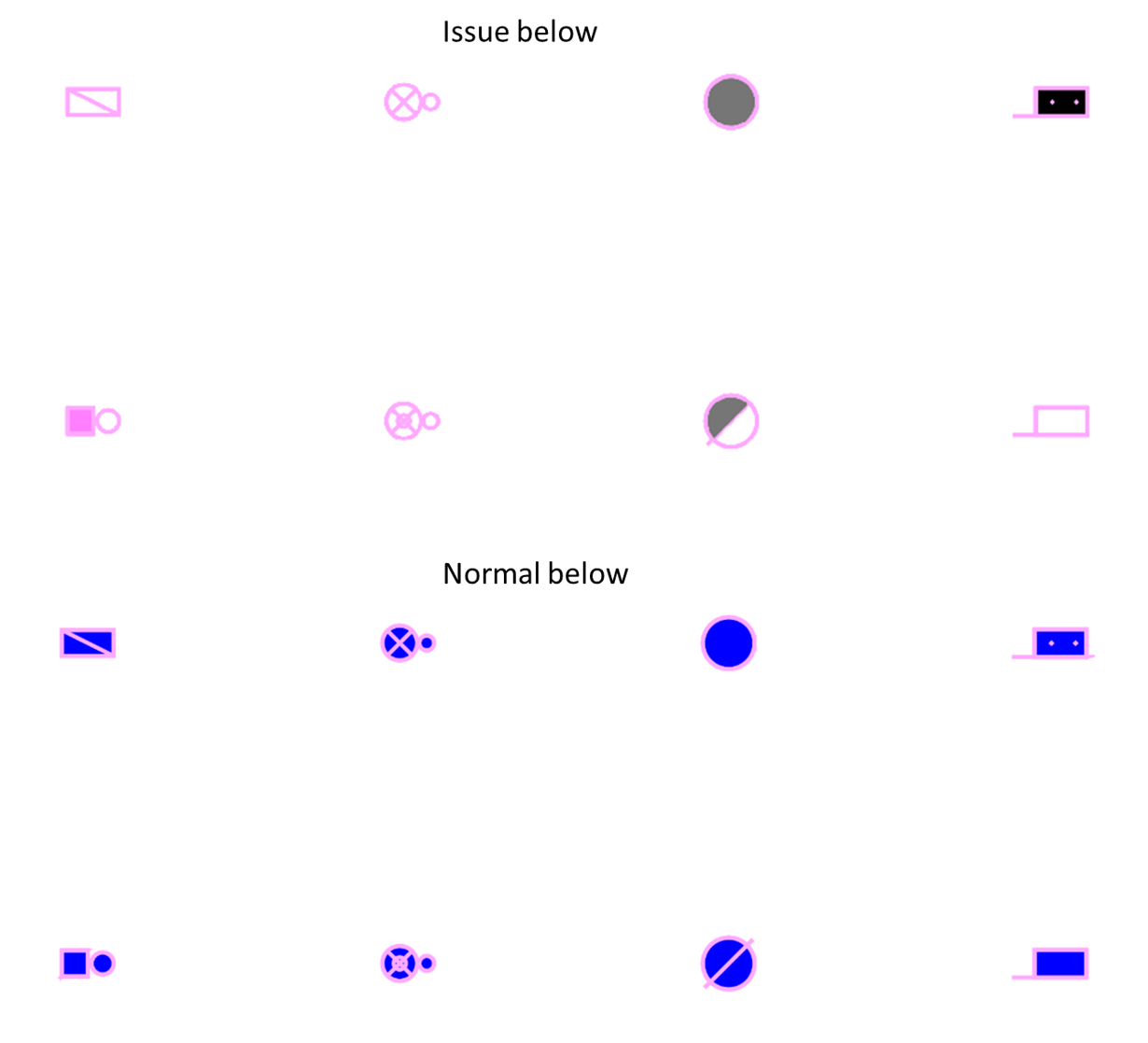
Here a picture showing the difference for a few symbols:

FME_question_Mapnik 

So my question is more about understanding what's going on, if it is expected due to changes in FME processing or if it is a bug.


7 replies

Userlevel 3
Badge +16

I tried your 2017 workspace, and was able to reproduce the issue. 

Running it in 2019.1 produces the expected result. In the log when running in 2021.1, the mapnik rasterizer reports:

Mapnik LOG> 2022-02-14 14:06:35: SVG PARSING ERROR:"SVG parse error: failed to parse <number> with value "none""

Mapnik is a plugin which may have been upgraded separately to its transformer version, because the dll files in Program Files\FME2021.1\plugins\mapnik are different between versions. The transformer just runs the plugin which comes with the FME version.


It's not the first bug I've encountered in mapnik, is there a way you can create SVG files which it is able to read correctly? 


Badge

Thanks for the help. I didn't think about the DLL, good point. This is probably the source of the difference. 

Is there a way to use the old DLL in a more recent install of FME? 


The parsing error isn't really important, this is due to something written in the style of the SVG, it doesn't support "stroke-width: none" but I already tried to change it to "stroke-width: 0" and it doesn't help. The error disappears but the issue is still here.


As I said, the SVG are generated from an Autocad DWG. There are things I can change in the process like dealing with the none stroke. But I can't change the fact that some Autocad symbols are made of multiple entities.


 Let's take an example with a particularly bothering symbol:

<svg xmlns="http://www.w3.org/2000/svg" viewBox="-1.25 -1.25 102.5 102.5"><g xmlns:fme="http://www.safe.com/fme" fill="none" stroke="black" stroke-width="0.0125" transform="translate(0,100) scale(1, -1)">
<g id="CAB014">
<path fme:transform="translate(0,0)" fme:autocad_block_name="CAB014" fme:autocad_block_number="232" fme:autocad_entity_handle="C124" style="fill: rgb(0,0,0); stroke: none; stroke-width: 0" d="M 100,50 l -0.190265,4.35779 -0.569347,4.32462 -0.944096,4.25854 -1.31166,4.16005 -1.66924,4.02991 -2.01412,3.86909 -2.34367,3.67882 -2.65538,3.46056 -2.94688,3.21596 -3.21596,2.94688 -3.46056,2.65538 -3.67882,2.34367 -3.86909,2.01412 -4.02991,1.66924 -4.16005,1.31166 -4.25854,0.944096 -4.32462,0.569347 -4.35779,0.190265 -4.35779,-0.190265 -4.32462,-0.569347 -4.25854,-0.944096 -4.16005,-1.31166 -4.02991,-1.66924 -3.86909,-2.01412 -3.67882,-2.34367 -3.46056,-2.65538 -3.21596,-2.94688 -2.94688,-3.21596 -2.65538,-3.46056 -2.34367,-3.67882 -2.01412,-3.86909 -1.66924,-4.02991 -1.31166,-4.16005 -0.944096,-4.25854 -0.569347,-4.32462 -0.190265,-4.35779 0.190265,-4.35779 0.569347,-4.32462 0.944096,-4.25854 1.31166,-4.16005 1.66924,-4.02991 2.01412,-3.86909 2.34367,-3.67882 2.65538,-3.46056 2.94688,-3.21596 3.21596,-2.94688 3.46056,-2.65538 3.67882,-2.34367 3.86909,-2.01412 4.02991,-1.66924 4.16005,-1.31166 4.25854,-0.944096 4.32462,-0.569347 4.35779,-0.190265 4.35779,0.190265 4.32462,0.569347 4.25854,0.944096 4.16005,1.31166 4.02991,1.66924 3.86909,2.01412 3.67882,2.34367 3.46056,2.65538 3.21596,2.94688 2.94688,3.21596 2.65538,3.46056 2.34367,3.67882 2.01412,3.86909 1.66924,4.02991 1.31166,4.16005 0.944096,4.25854 0.569347,4.32462 0.190265,4.35779 z "/>
<ellipse fme:transform="translate(0,0)" fme:autocad_block_name="CAB014" fme:autocad_block_number="232" fme:autocad_entity_handle="C125" style="fill: none; stroke: rgb(0,0,0); stroke-width: 2.5" rx="50" ry="50" transform="translate(50,50) rotate(0.00)"/>
</g></g></svg>

Here this is a simple case, the symbol is a solid circle with an outline stroke. At the origin, the Autocad symbol is made of a hatch and an ellipse, this is why you see two autocad entities mentioned in the SVG. MapnikRasterizer, in the recent version causing the issue, will always ignore the filling of the SVG. In the marker parameter, if I set anything in the fill section, it will be ignored. Anything I set in the line section is performed. Is there an issue with how the symbol is converted to SVG?


Badge

I may have found the issue, the first <g> element has a none fill, it is blocking the filling by the transformer:

<g xmlns:fme="http://www.safe.com/fme" fill="none" stroke="black" stroke-width="0.0125" transform="translate(0,100) scale(1, -1)">


Giving it a color manually enable the filling in FME by mapnik.


I will check where it comes from

Badge

After a few tries, it seems that this element is entirely made up by FME during the writing. I don't think there is any control on that. It is useless to specify that in the svg to have a empty background and it messes with mapnik rasterizer.

Userlevel 2
Badge +10

Hi @alexandre​ thanks to your thorough investigation, I can confirm I'm seeing the same issue. Removing the fill="none" SVG attribute results in a successful output from the MapnikRasterizer.


I'll be looking to file a bug report/enhancement request to resolve this issue in future releases of FME, however I do need just one piece of supporting information. That being the AutoCAD to SVG workspace you used to create the SVG files. Would you be willing to share the Workspace and Source Data for that process with us so that we can fully reproduce this issue? If you're not comfortable sharing the data publicly here, you can also upload the data to our Safe Software Support FTP.

Badge

Hi @alexandre​ thanks to your thorough investigation, I can confirm I'm seeing the same issue. Removing the fill="none" SVG attribute results in a successful output from the MapnikRasterizer. 


I'll be looking to file a bug report/enhancement request to resolve this issue in future releases of FME, however I do need just one piece of supporting information. That being the AutoCAD to SVG workspace you used to create the SVG files. Would you be willing to share the Workspace and Source Data for that process with us so that we can fully reproduce this issue? If you're not comfortable sharing the data publicly here, you can also upload the data to our Safe Software Support FTP.

Thanks a lot, here the workbench I use to produce the SVG.


I added the solution I implemented as a python script running at the end.


If it interests someone, it is simply overwriting to remove the issue by brute force:

import os
import fme
 
directory = fme.macroValues['cSvgFolderPath']
fileNames = os.listdir(directory)
 
for f in fileNames:
    if f.endswith(".svg"):
        filepath=directory+'/'+f
        fl=open(filepath).read()
        open(filepath, 'w').write(fl.replace('fill="none" ',''))


Userlevel 2
Badge +10

Thanks a lot, here the workbench I use to produce the SVG.


I added the solution I implemented as a python script running at the end.


If it interests someone, it is simply overwriting to remove the issue by brute force:

import os
import fme
 
directory = fme.macroValues['cSvgFolderPath']
fileNames = os.listdir(directory)
 
for f in fileNames:
    if f.endswith(".svg"):
        filepath=directory+'/'+f
        fl=open(filepath).read()
        open(filepath, 'w').write(fl.replace('fill="none" ',''))


Hi @alexandre

I filed a bug report regarding this issue. For your reference, the issue number is FMEENGINE-72567. If a fix is released in a new version of FME, you will be notified here. 


Thanks.

Reply