Question

Profile and grid

  • 21 February 2020
  • 10 replies
  • 21 views

@garydlester

Hi !

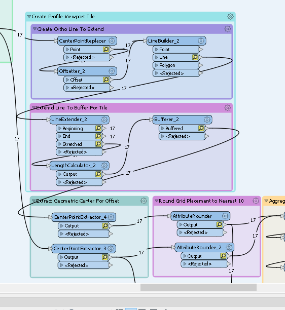
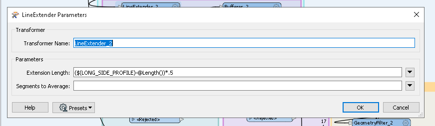
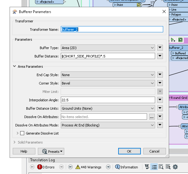
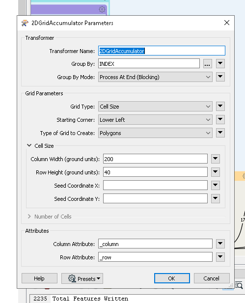
I'm trying to do an elevation profile of some network lines to be exported in AutoCAD. But I'm not being able to adapt the labels and grid so as to be able to view the profile of each section.Could you please help me.

Thank you very much.


10 replies

Badge +5

@garydlester you might need to provide a little more ‘incentive’ if you want it done for you ;)

Can you detail your particular workspace issues?

@sati27 Thanks for your question, let me look at your workspace and I will get back with you.

@sati27 can you save this workspace as a template (.fmwt) so that I can just run it and see what is going on, thanks.

@sati27 do you have ground elevation points? Also some lines need to be breaklines, To make a profile take ground elevation points and create DEM then sample the DEM along your polyline routes, then create vertices swap the station for x and the elevation for y then get length of line and the ymax-ymin use these values along with the centerpoint of your profile to create viewport box, if this makes sense,

Hi @garydlester !

Thank you in advance for your help! Please find attached .fmwt file. Kind regards.

Profilescreator_V1.fmwt

@sati27 do you have ground elevation points? Also some lines need to be breaklines, To make a profile take ground elevation points and create DEM then sample the DEM along your polyline routes, then create vertices swap the station for x and the elevation for y then get length of line and the ymax-ymin use these values along with the centerpoint of your profile to create viewport box, if this makes sense,

@garydlester, I understand what you are trying to tell me. I'm new to FME and it gonna takes me some more time to do it. I have a csv file with coordinates and two altitudes for ground and underground. See attached file. I don't know if its enough to make the fmwt works! Thanks coordpts.csv

@sati27 do you have ground elevation points? Also some lines need to be breaklines, To make a profile take ground elevation points and create DEM then sample the DEM along your polyline routes, then create vertices swap the station for x and the elevation for y then get length of line and the ymax-ymin use these values along with the centerpoint of your profile to create viewport box, if this makes sense,

Altitude_Reseaux.dgn

@garydlester, Here is the 3D network file.

@sati27 I look at your workspace and it look like you are trying to make sheet size 20 in length 20' or 20 m is a small sheet you will need to accommodate the smaller length


Adjust the length extender


This LONG_SIDE_PROFILE parameter value should be about 1.2 x's your chop length which was set at 20,


This SHORT_SIDE_PROFILE parameter is the height of your profile so this need to be about 10 from the data I saw in the workspace

Also you need to set up the grid accumulator to work with small scale currently, it is building blocks that are 20x200, so change the accumulation settings. I would just build 1 x 5 blocks if you are doing size 20 sheets.


Then you are going to have to set the scale in the viewport,

Hi @garydlester !

Thanks a lot, it works as I wanted it to be!

Hi @garydlester !

Thanks a lot, it works as I wanted it to be!

Nice, good work, you are most welcome.

Reply