Question

shift lines on another line


hey guys,

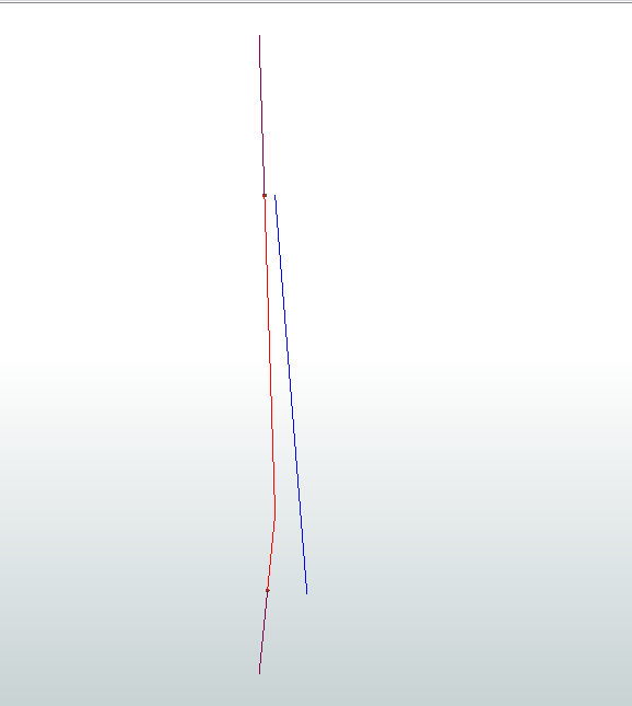
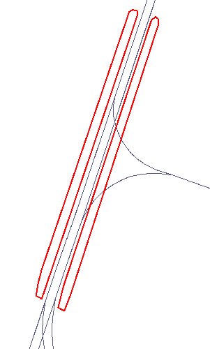
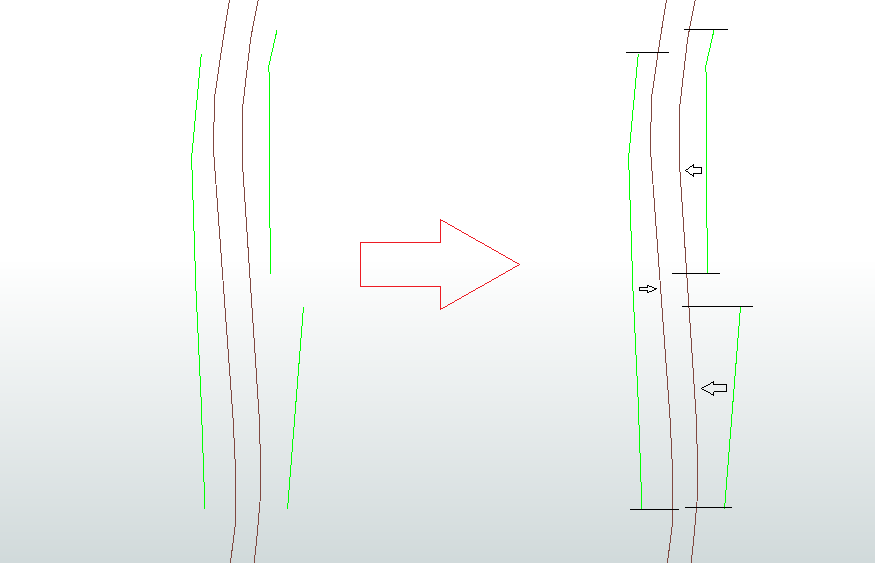
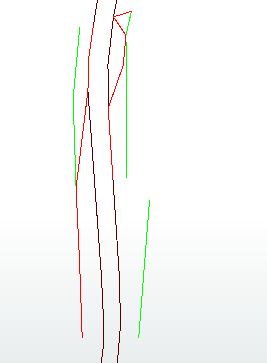
i want to shift single lines (green) on another line (brown) or identify the area, where the singles lines would lie on, if I shift them on the brown line.

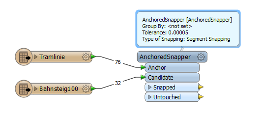
I tried to do it with the AncorchedSnapper, but it doesn't work very well.

Is it possible with FME?

Thanks a lot

Julia


10 replies

Badge +22

Were you using vertex or segment snapping?

Userlevel 4

As @jdh hints at, you should try both vertex and segment snapping, but I suspect segment snapping is your best bet. Also make sure that the tolerance (in ground units) is sufficiently large for all the vertices.

@jdh i used segment snapping.

@david_r i tried different tolerances, but it doesn't worked. Is there an alternative solution for my problem?

Userlevel 4

@david_r i tried different tolerances, but it doesn't worked. Is there an alternative solution for my problem?

Can you post a small dataset here to test with?

data.zip

I hope this is what you asked for @david_r

the candidates ("Bahnsteig100") are very different, but i would be very happy, if it would work with the "simple" lines.

Userlevel 1
Badge +12

I think you need to do some pre-processing.

So create points for the start and end position of the line you want to snap. Use the neighbourfinder to find the closest "anchor". At the location where the point connects to the anchor, create the point.

EDITED:

Use the pointofline transformer to split. Make sure it has two points on it and that is the line you keep.

Here is a workbench that does what you have shown in the

pictures above.snappingtoline.fmw

Userlevel 4

The problem is two-fold, I think.

First, you need to increase the tolerance. Maybe consider reprojecting both datasets into UTM before the AnchoredSnapper so that you can specify the tolerance in meters rather than decimal-degrees.

Secondly, you have cases like this, which the AnchoredSnapper will probably not treat in an ideal way:

I've done something similar but it ended up being rather complex in the end. Some steps include

  • explode the platform vertices into separate points
  • project each point onto all the closest rails
  • isolate the rail that shares the longest distance with the platform
  • find the min/max distance of the platform points on the previously found rail
  • clip the rail at the min/max distance points, this replaces the platform geometry

I'm sure there are different ways of doing it, but it will depend on your requirements.

Actually, if your dataset isn't too big you could consider doing some manual pre-processing which would give you much better results with less effort. If you could attach an attribute to each platform that uniquely identifies which rail-line it belongs to, you could use that as a Group By in the AnchoredSnapper.

Badge +3

Seems it depends on what u actualy want.

Look for similarities? (most intensive to solve)

Look for the projection of the green on the blue lines (wich is what Todd does) easy to solve

Or project the length of the green line on the blue. easy to solve.

Or non of above.

Maybe you want to do following.

1. project the end- and beginpoint of the green lines on the blue line. ( by neighbourfinder)

2. create line from 1 projected point to begin- or endpoint. Create line from both projected points. (using vertexcreators)

3 rotate green line by the angular difference of both lines.

(if you don't want to do basic goniometry u can use the azimuthcalculator on both lines and substract the angles)

Reply