Question

Assign text string to line as new attributes - neighbour finder 1 to 1 challenge

  • 20 August 2017
  • 9 replies
  • 6 views

Badge

In the drawing screenshot below , lines represent drill holes. Geometry of these polyline features have been correctly drafted based on surveyed co-ordinates. Unfortunately key research data for HoleID , date of drilling and length of hole has only been placed as point text string on the drawing, the drill holes are not attributed.

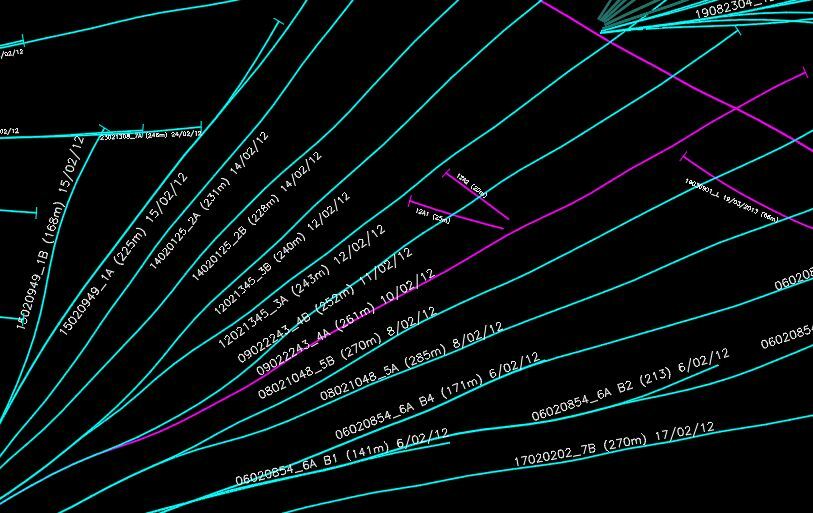
The alignment (rotation) of the text string is generally within +/- 5 degrees of the alignment (angle) of the polyline , and it is also generally placed within 5m of the line. Due to the drilling pattern , using simply a neighbour finder produces inconsistent results , mainly because there may be more than 1 candidate text point within the finders' proximity. In some locations , drill holes are in such close proximity to each other, that the finder returns duplicate matches or matches the holes at right angles.

Ideally , the desired outcome would be each line matches one unique text string, taking advantage of the rotation of the text and the line angle to exclude text that may belong to other holes (for example holes at right angles). It appears from other posts that a neighbour finder mode for a 1 to 1 match would be highly valued by many users. Reversing base and candidates has been attempted here too.

Once the text is correctly matched to the line , it appears that a combination of attribute splitter / string searcher / regex may be able to allocate the text HoleID, Date and Length to new attributes of the line.This outcome would greatly assist the research effort to identify the relative effect of different drilling patterns at different times.

Thanks in advance for your consideration and assistance.


9 replies

Userlevel 5
Badge +25

There's an AzimuthCalculator custom transformer that you could use to determine the angles of the lines, which would give you that extra layer of control. But if you look at the most lower left label, right by a junction, that would be a very tricky situation. Or even worse: the next one up the line, where it branches off to a very short line.

In cases like this I would be very weary of accepting automatic results. Even if you manage to make a 1-to-1 match there's no guarantee it'll always be the correct match.

Badge

There's an AzimuthCalculator custom transformer that you could use to determine the angles of the lines, which would give you that extra layer of control. But if you look at the most lower left label, right by a junction, that would be a very tricky situation. Or even worse: the next one up the line, where it branches off to a very short line.

In cases like this I would be very weary of accepting automatic results. Even if you manage to make a 1-to-1 match there's no guarantee it'll always be the correct match.

Thanks @redgeographics. Yes agree, all results will have to be thoroughly vetted. I have tried both azimuthcalculator and lengthcalculator as methods of eliminating potential mismatches, perhaps even using a group by function within the neighbour finder to restrict ranges of potential matches even further. With over 3000 lines to test, I'm hoping there is at least an 80/20 benefit to start with an automated process.


Badge +8

Hello @pat_uow,

I need to ask which format are you reading from before I can answer any further, thanks.

Lyes

Badge

Hello @pat_uow,

I need to ask which format are you reading from before I can answer any further, thanks.

Lyes

All input features are being read from a single AutoCAD dwg file.


Badge +8
All input features are being read from a single AutoCAD dwg file.


I would then start by seperating the features based on the ACAD_color attribute . To have a better control over the text I would use PointOnLineOverlayer transformer, it works wonders. If you could share a portion of the file, that would be even better .


Badge
I would then start by seperating the features based on the ACAD_color attribute . To have a better control over the text I would use PointOnLineOverlayer transformer, it works wonders. If you could share a portion of the file, that would be even better .


Thanks @gisinnovationsb.


Good idea re colours, however the line colours reflect the drawing layers related to the function of the hole, then all text is grouped together in a single separate layer.


I will try a point on line overlay but I'm thinking either the line or the text or both will probably need to be buffered to create the match on alignment.


Unfortunately the data set is protected by confidentiality requirements so I'm not at liberty to share it, but really appreciate the help.


Badge +8
Thanks @gisinnovationsb.


Good idea re colours, however the line colours reflect the drawing layers related to the function of the hole, then all text is grouped together in a single separate layer.


I will try a point on line overlay but I'm thinking either the line or the text or both will probably need to be buffered to create the match on alignment.


Unfortunately the data set is protected by confidentiality requirements so I'm not at liberty to share it, but really appreciate the help.


you just need to set the distance of the point from the line and you are all done. there is no need to create a buffer.


Badge

Hello @pat_uow,

I need to ask which format are you reading from before I can answer any further, thanks.

Lyes

Hi @gisinnovationsb , just to let you know I'm investigating a potential issue with the point on line overlayer causing the translation to fail in 2017.0.1. Safe have recommended updating to 2017.1 to see if that resolves the issue.
Badge +8
Hi @gisinnovationsb , just to let you know I'm investigating a potential issue with the point on line overlayer causing the translation to fail in 2017.0.1. Safe have recommended updating to 2017.1 to see if that resolves the issue.
hi @pat_uow


upgrading is the right thing to do. Hope it will work for you.


Reply