Solved

extracting surface from 3d volume

  • 31 March 2016
  • 6 replies
  • 12 views

Badge

Given the attached dxf containing 3d faces (fme_geometry: fme_aggregate), I'm trying to produce a surface of the top of the 3d shape.

The 3d shapes will contain holes.

I'm not having much success so hoping someone can point me in the right direction.

Thanks!

icon

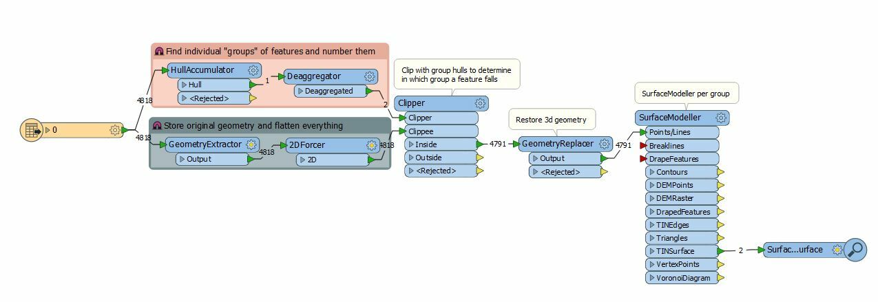
Best answer by takashi 31 March 2016, 09:33

View original

6 replies

Userlevel 2
Badge +17

Hi @stevenjh, in my observation, the features from your sample data can be classified into these three types.

  • Top: non-vertical triangular faces, right-hand-rule
  • Bottom: non-vertical triangular faces, left-hand-rule
  • Vertical: vertical triangular faces, any rule

In this condition, the faces can be filtered by the sign of z-component value of the normal vector (let's say "vz"). i.e. vz is equal to 0 if the face is vertical, and Top or Bottom can be determined by whether vz is negative or not. In the actual processing, a tolerance should be considered to determine whether a face is vertical, since computational error cannot be avoided always.

From the above consideration, this would be a possible approach.

  1. Once transform all the faces into 3D triangle polygons.
  2. Calculate the normal vector based on coordinates of 3 vertices for each triangle.
  3. Restore the faces (transform the triangles into faces).
  4. Classify them into Top, Bottom, and Vertical by the z-component value of the normal vector.
  5. Aggregate them to create surface (IFMEMultiSurface) geometries for each part.

See also the attached example workspace: extract-top-surface-example.fmwt (FME 2015.1.3+)

Note that the approach is only applicable to the same condition as the sample. Different condition requires different approach. First of all, need an inspection about the source data with FME Data Inspector.

Userlevel 4
Badge +25

Creating the surface itself can be done with the SurfaceModeller, but the trick here is to seperate out the 2 disjoint sets of features. I've done that through a HullAccumulator / Clipper approach, which required me to store the original geometry, flatten the data (because the Clipper doesn't do 3d) and then restore the original geometry afterwards. This gives every face an attribute which indicates in which set it falls (i.e. which part of the hull that was generated) and then the SurfaceModeller is set to group by that attribute. Hope this helps.

knipsel.jpg dxf-to-surface.fmw

Badge

@takashi that is really cool, thanks for putting that together, I need to come back to it and understand how the pieces are working. @redgeographics I was trying that approach and was not ending up with smooth surfaces on top.


Thanks again!

Userlevel 4
Badge +25

@takashi that is really cool, thanks for putting that together, I need to come back to it and understand how the pieces are working. @redgeographics I was trying that approach and was not ending up with smooth surfaces on top.


Thanks again!

The surface tolerance and interpolation method parameters of the SurfaceModeller most likely will help smoothing it out, I have to admit they're often a case of trial and error for me.

Userlevel 2
Badge +17

The surface tolerance and interpolation method parameters of the SurfaceModeller most likely will help smoothing it out, I have to admit they're often a case of trial and error for me.

Hi @redgeographics, I agree that your approach can be applied in many cases, but I think the most critical issue in this case is that the source geometries represent mainly two surfaces (top and bottom) of three-dimensional objects. It seems that the SurfaceModeller uses every vertex of both the top and bottom surfaces to create a TIN surface. Therefore, the resulting surface might not represent the top surface of the object.

Userlevel 4
Badge +25

Hi @redgeographics, I agree that your approach can be applied in many cases, but I think the most critical issue in this case is that the source geometries represent mainly two surfaces (top and bottom) of three-dimensional objects. It seems that the SurfaceModeller uses every vertex of both the top and bottom surfaces to create a TIN surface. Therefore, the resulting surface might not represent the top surface of the object.

Aaah, I hadn't realized they were top and bottom... my bad.

Reply